


21
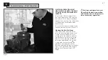
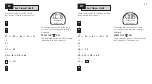
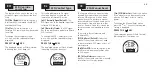
Fig. 8
ELECTRICAL OPERATION MUST
NOT TAKE PLACE UNTIL THE BASIC
SETTINGS HAVE BEEN MADE AND
CHECKED.
The actuator’s Basic Settings affect
the correct operation of the valve by
the actuator. If the actuator has been
supplied with the valve, the valve maker
or supplier may have already made
these settings.
This instruction assumes setting mode
has been entered.
Refer to section 7.6.
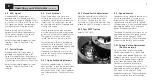
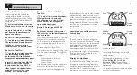
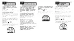
Viewing the Basic Settings
With the actuator mounted on the
valve, the power supply on and Local
or Stop control selected, point the
setting tool at the actuator indicator
window from a distance of no more
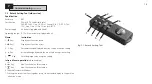
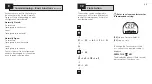
than 0.75m. By pressing the
m
key
and, when appropriate, the
k
key,
it is possible to move through the
procedure, displaying the various
functions and their settings as shown in
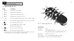
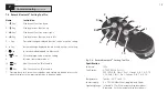
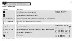
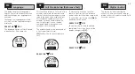
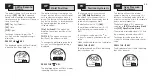
Fig. 8.1.The right-hand side of Fig.8.1
explains the function of each LCD
display.
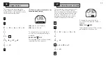
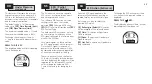
Settings and operation must
be verified by electric operation
and function test of the actuator
to ensure correct operation.
8
Commissioning – Basic Functions


