


Synergy 1 and Synergy 100 Maintenance Guide (v16-S1)
Software Upgrades • 3–3
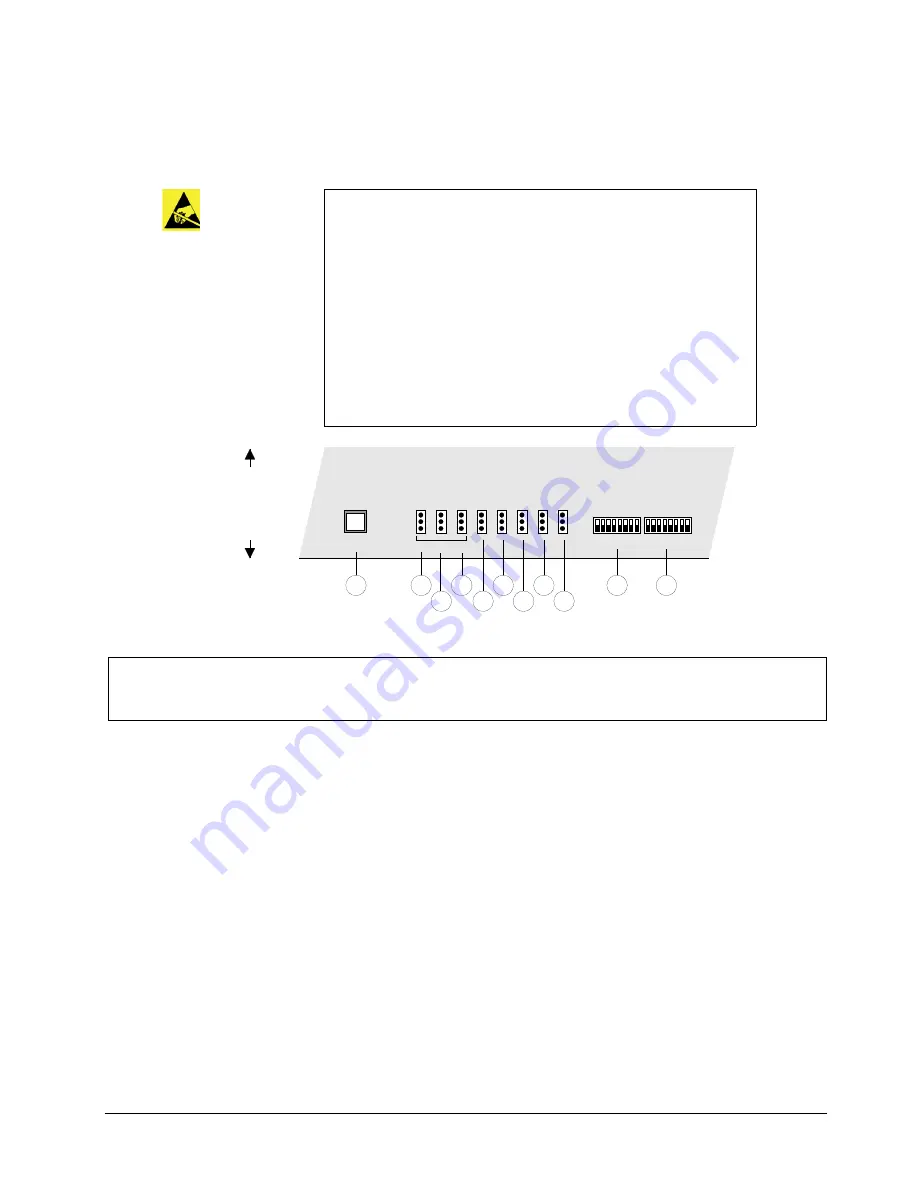
Synergy 1 Control Panel Jumpers and Switches
The following diagram illustrates the location of jumpers and switches on the front edge of the
Control Panel CPU Board
:
Control Panel Jumpers and Switches
1. JP2, Panel Type
Jumper
JP2
works with
JP3
and
JP4
to set the control panel type. Please leave it in the
default
Down
position.
2. JP3, Panel Type
Jumper
JP3
works with
JP2
and
JP4
to set the control panel type. Refer to the
following table for details.
Caution
All product servicing should be carried out by qualified service
personnel.
To gain access to the control panel jumpers, as outlined in the section,
“
Synergy 1 Control Panel Jumpers and Switches
will be necessary to remove the safety barrier from the inside of the
Control Panel’s tub. The equipment still presents a safety hazard with
the power switches in the
OFF
position. To avoid electrical shock,
disconnect all A/C power cords from the rear of the panel before
removal of this barrier.
Service barriers within this product are intended to protect the operator
and service personnel from hazardous voltages. For continued safety,
replace all barriers after servicing.
1) JP2, Panel Type
2) JP3, Panel Type
3) JP4, Panel Type
4) JP5, Reserved
5) JP6, Reserved
6) JP7, Reserved
7) JP8, Reserved
8) JP9, Panel Redundant Power
9) DIP Switch 1, Reserved
10) DIP Switch 2, Reserved
11) Reset Button
Rear Connector Panel
Control Panel Front
Control Panel CPU Board
JP2 JP3 JP4 JP5 JP6 JP7 JP8 JP9
9
10
1
2
3
5
6
7
8
DIP SW1
DIP SW2
PANEL TYPE
RESET
11
4
Summary of Contents for Synergy 1
Page 1: ...Ross Video Limited Synergy 1 and Synergy 100 Maintenance Guide Software Version 16 S1...
Page 10: ......
Page 16: ...vi Contents Synergy 1 and Synergy 100 Maintenance Guide v16 S1...
Page 24: ...1 8 Introduction Synergy 1 and Synergy 100 Maintenance Guide v16 S1...
Page 70: ...3 24 Software Upgrades Synergy 1 and Synergy 100 Maintenance Guide v16 S1...
Page 108: ...5 12 Frame Processor CPU Board Synergy 1 and Synergy 100 Maintenance Guide v16 S1...
Page 122: ...6 14 Working with Installed Options Synergy 1 and Synergy 100 Maintenance Guide v16 S1...
Page 142: ...8 14 Power Supplies Synergy 1 and Synergy 100 Maintenance Guide v16 S1...
Page 172: ...9 30 Calibration and Diagnostics Synergy 1 and Synergy 100 Maintenance Guide v16 S1...
Page 186: ...10 14 Control Panel Boards Synergy 1 and Synergy 100 Maintenance Guide v16...
Page 230: ...13 20 Miscellaneous Options Synergy 1 and Synergy 100 Maintenance Guide v16 S1...
Page 240: ...IX 10 Index Synergy 1 and Synergy 100 Maintenance Guide v16 S1...


