background image

76

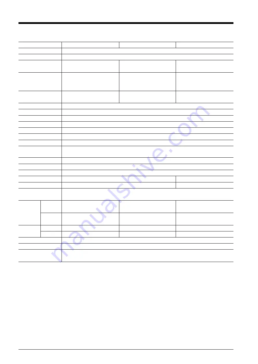
GX-400

Mechanism

Driving method

Maximum cutting area

Acceptable media widths

Width of material that
can be cut off

Tools

Maximum cutting speed

Cutting speed

Blade force

Mechanical resolution

Software resolution

Distance accuracy 

(*1)

Repetition accuracy

(*1)(*2)(*3)

Interface

Replot memory

Instruction system

Power supply

Power consumption

Acoustic noise level

Dimensions

Weight

Operating temperature

Operating humidity

Accessories

Special blade for CAMM-1 series

During cutting: 850 mm/sec. (in all directions)   During tool-up: 1202 mm/sec. (in 45

°

 direction)

10 to 850 mm/sec. (in increments of 10 mm/sec.)

20 to 350 gf

0.0125 mm/step (0.000492 in./step)

0.025 mm/step (0.000984 in./step)

Error of less than 

±

 0.2% of distance traveled, or 0.1 mm (0.00394 in.), whichever is greater

0.1 mm or less

Serial  (RS-232C-compatible), USB (Rev 1.1)

2 MB (buffer size: 8 MB)

Dedicated system (CAMM-GLIII-compatible)

                              AC 100V to 240V 

±

 10% 50/60 Hz 1.2A

     AC 100V to 240V 

±

 10% 50/60 Hz 1.1A

Cutting mode: 62dB (A) or less          Standby mode: 40dB (A) or less

(according to ISO 7779)

Width: 737 mm (29 in.)

Length: 24998 mm (984-1/8 in.)

Min. 50 mm (2 in.)/ Max. 915 mm (36 in.)

(50 to 540 mm (2 in. to 21 in.),

582 to 915 mm (23 in. to 36 in.))

0 to 812 mm (0 in. to 32 in.)

GX-300

Main unit

With stand

Main unit

With stand

*1
According to material and cutting conditions as specified by Roland DG Corp. (refer to the following page).
*2
Excluding stretching/contraction of the material
*3

Range for assured repetition accuracy

For materials with a width exceeding 610 mm (24 in.):  Length 4,000 mm (157-7/16 in.)  (GX-500/400 only)
For materials with a width of 610 mm (24 in.) or less :  Length 8,000 mm (314-15/16 in.)

Width: 1000 mm (39 in.)

Length: 24998 mm (984-1/8 in.)

Min. 90 mm (3-1/2 in.) /

Max. 1178 mm (46 in.)

0 to 1067 mm (0 in. to 42 in.)

Width: 1195 mm (47 in.)

Length: 24998 mm (984-1/8 in.)

Min. 90 mm (3-1/2 in.) /

Max. 1372 mm (54 in.)

0 to 1270 mm (0 in. to 50 in.)

GX-500

Media-movement method

Digital control servo motor

1144 mm (W) x 264 mm (D) x 398 mm (H)

(45-1/16 in. (W) x 10-3/8 in. (D) x 15-11/16 in. (H))

1144 mm (W) x 727 mm (D) x 1113 mm (H)

(45-1/16 in. (W) x 28-5/8 in. (D) x 43-13/16 in. (H))

26 kg (57.3 lb.)

44 kg (97 lb.)

1407 mm (W) x 264 mm (D) x 398 mm (H)

(55-3/8 in. (W) x 10-3/8 in. (D) x 15-11/16 in. (H))

1407 mm (W) x 727 mm (D) x 1113 mm (H)

(55-3/8 in. (W) x 28-5/8 in. (D) x 43-13/16 in. (H))

31 kg (68.3 lb.)

51 kg (112.4 lb.)

1602 mm (W) x 264 mm (D) x 398 mm (H)

(63-1/16 in. (W) x 10-3/8 in. (D) x 15-11/16 in. (H))

1602 mm (W) x 727 mm (D) x 1113 mm (H)

(63-1/16 in. (W) x 28-5/8 in. (D) x 43-13/16 in. (H))

35 kg (77.2 lb.)

55 kg (121.2 lb.)

5 to 40

°

C (41 to 104

°

F)

35 to 80% (non-condensing)

Power cord, blade holder (XD-CH2), pin, blade, alignment tool, cable clamp, replacement blade for separating knife,

USB cable, Roland software package CD-ROM, setup guide, user’s manual

9-2  Specifications

Approx. 100W

 Approx. 95W

Summary of Contents for Camm-1 Pro GX-300

Page 1: ...d the specifications of this product are subject to change without notice The operation manual and the product have been prepared and tested as much as possible If you find any misprint or error pleas...

Page 2: ...have the proper outlet installed by a qualified electrician Check with qualified electrician or service personnel if the grounding instructions are not completely understood or if in doubt as to whet...

Page 3: ...rial Cut Material Etc 39 4 5 Repeating the Same Cutting 40 4 6 Front Loading 41 4 7 The Overcut Feature 44 4 8 The Memory Feature 45 4 9 The Crop Mark Feature 47 4 10 Performing Test Feed of Material...

Page 4: ...determined by the design contained within the triangle The symbol at left means danger of electrocution The symbol alerts the user to items that must never be carried out are forbidden The specific th...

Page 5: ...necktie necklace or loose clothing Bind long hair securely Such items may become caught in the machine resulting in injury Caution cutting tool This machine has an internal tool To avoid in jury handl...

Page 6: ...aged Using a damaged article may result in fire or electrical shock When using an extension cord or power strip use one that adequately satisfies the machine s ratings for voltage frequency and curren...

Page 7: ...he power cord plug and electrical outlet Never place any object on top or subject to damage Never bend or twist with undue force Never pull with undue force Never bundle bind or roll up Never allow to...

Page 8: ...d their warnings Also never remove the labels or allow them to become obscured Warning Labels Caution Moving Carriage The cutting carriage moves at high speed and pose a hazard Keep your hands away fr...

Page 9: ...To Ensure Safe Use 7...

Page 10: ...le dessin l int rieur du triangle Le symbole gauche signifie danger d lectrocution Le symbole avertit l utilisateur de ce qu il ne doit pas faire ce qui est interdit La chose sp cifique ne pas faire...

Page 11: ...dents L utilisation incorrecte peut causer des blessures PRUDENCE Faire preuve de prudence pour viter l crasement ou le coincement La main ou les doigts peuvent tre cras s ou coinc s s ils entrent en...

Page 12: ...fiche et la prise lectrique correctement et avec soin Ne jamais utiliser un article endommag car cela pourrait causer un incendie ou un choc lectrique Si une rallonge ou une bande d alimentation lectr...

Page 13: ...la fiche ou sur la prise car cela risque de les endommager Ne jamais plier ni tordre le c ble avec une force excessive Ne jamais tirer sur le c ble ou la fiche avec une force excessive Ne jamais plie...

Page 14: ...tissements Ne jamais retirer les vignettes et ne pas les laisser s encrasser Vignettes d avertissement Attention Chariot mobile Le chariot de coupe se d place tr s rapidement et peut tre dangereux Ten...

Page 15: ...so cause malfunction or breakdown Main unit This Machine Is a Precision Device Handle carefully and never subject the machine to impact or excessive force Install in a Suitable Location Install in a l...

Page 16: ...14...

Page 17: ...ers grip the material and move it forward and backward Movable Pinch Roller Middle This is used when cutting materials with a width of 762 mm 30 in or more At this time it is set at the center of the...

Page 18: ...ressing this repeatedly switches sequentially amang the present cutting condition the menu mode and the width display screen See 6 3 PAUSE Key When pressed once this temporarily halts cutting in progr...

Page 19: ...21 in 582 to 915 mm 23 in to 36 in There is no special restriction on length vertical dimension as long as it is 200 mm 7 7 8 in or more You can also use flat material such as standard size and piece...

Page 20: ...for the GX 500 400 300 1 Mount the shafts on the sheet hangers to match the outer diameter of the roll material If mounted at an incorrect position the roll may fall off 2 Place the roll material on...

Page 21: ...e moved within this range When loading material with a width other than one indicated above move the right hand movable pinch roller 1 Position of the pinch roller middle when using material with a wi...

Page 22: ...ble Pinch Roller Left Movable Pinch Roller Right Movable Pinch Roller Middle The right hand movable pinch roller can be moved within this range When loading material with a width other than one indica...

Page 23: ...approx 915 mm Material GX 300 Material Loading Position The right hand movable pinch roller can be moved within this range When loading material with a width other than one indicated above move the r...

Page 24: ...g grit roller If the pinch rollers do not move smoothly try moving them by grasping near the base of the sheet loading lever at the back of the unit Load the material so that it is straight If the mat...

Page 25: ...you need to pull out the required length of material from the roll For more information refer to Material Test Feed in 3 5 Starting Cutting 3 2 Installing a Blade Do not touch the tip of the blade wi...

Page 26: ...you perform the actual cutting carry out a cutting test to check the cutting quality for the material Examine the result of the cutting test adjust the value of the blade force and cutting speed Repe...

Page 27: ...g cut Take care not to set the blade force excessively high Adjusting the Blade Force Examine the result of the cutting test and adjust the blade force accordingly After using the operation panel to s...

Page 28: ...lay the screen in the figure 2 Use the and keys to adjust the value then press the ENTER key to enable the setting Incorrect cutting conditions may cause symptoms such as those described below 3 4 Set...

Page 29: ...ial loading has been completed 1 Make sure the brake is released 2 Press the MENU key several times until the screen shown in the figure appears 3 Press the key 4 Press the key Press the key several t...

Page 30: ...r Cutting stops and the screen shown in the figure appears on the display Pausing Cutting Operations If you want to pause cutting follow the procedure described below 20cm s 50gf 0 250mm A Downloading...

Page 31: ...ration pauses and the screen shown in the figure appears 2 If you want to change the cutting speed press the SPEED key If you want to change the blade force press the FORCE key 3 Use the and key to ch...

Page 32: ...ol carriage 4 Press the pin and remove the blade from the blade holder As debris of material or paste might cling to the tip of a used blade wipe it with a soft cloth to remove them 1 Press the MENU k...

Page 33: ...de Extension Use the following dimension as a rough estimate for setting the amount of blade extension Amount of blade extension Thickness of the material portion 2 Thickness of the carrier paper Adju...

Page 34: ...ng the blade offset we recommend first adjusting the blade force and the amount of blade extension Changing the Speed When Raised Up Speed With this machine you can set the speed for movement to the n...

Page 35: ...ether cutting quality is emphasized This is also effective in preventing misalignment and motor errors when cutting heavy material 1 Press the MENU key several times until the screen shown in the figu...

Page 36: ...for SELECT SHEET on the operation panel when loading material ROLL Set near the left hand pinch roller F EDGE Set at the front left edge of the material R EDGE Set at the inner left edge of the mater...

Page 37: ...near the left pinch roller When the length of the material is 1 600 mm 63 in or longer the material is determined to be roll material The origin point is set in the same way as for ROLL above 0 0 30...

Page 38: ...settings to match the program you re using When this is set to 90deg on the operation panel then the CAMM 1 driver s Rotate setting must be set to Rotate off When rotated 90 degrees the X axis Y axis...

Page 39: ...gin point is the margin See The Location of the Origin Point Immediately After Loading Material elsewhere in this section When you have separated the material using the SHEET CUT key this is the value...

Page 40: ...r at the center between the left and right pinch rollers If a grit mark is present between the left and right pinch rollers position the middle pinch roller above the corresponding grit roller 4 While...

Page 41: ...AREA 1 0m 5 0m W 500mm L 0mm Press 4 4 Loading Flat Material Standard size Material Cut Material Etc In addition to roll material you can also load flat material such as piece material on this machine...

Page 42: ...e The Replot feature performs cutting using all the data stored in the machine s replot memory This means that when you perform replotting then before you send the data to be replotted from the comput...

Page 43: ...ial 1 Refer to 3 1 Loading the Material Roll Material and load the material 2 At SELECT SHEET select either ROLL or R EDGE Do not select F EDGE 3 Follow the steps in About the Origin Point and the Cut...

Page 44: ...ver Setting the Cutting Area Using the Operation Panel Pinch Roller No cutting area Pinch Roller Front View Material Material Cutting area 30 mm 1 3 16 in Depends on length when loaded 0 0 30 mm 1 3 1...

Page 45: ...oward the back without any cutting performed A new origin point is set and the cutting area of the size you had set in step 2 is made available automatically Cutting then starts When cutting has finis...

Page 46: ...n excess margin of 1 mm 0 04 in from the first and last line segments This is effective when you want to finish with angles that are especially sharp such as when cutting thick material This should no...

Page 47: ...to make the settings for cutting conditions matched to the tool and material in use You can set the following five types of parameters Blade force FORCE key Offset Menu mode OFFSET Cutting speed SPEE...

Page 48: ...settings for cutting conditions returning them to their factory defaults Please note that all user numbers from 1 to 8 are deleted This resets to their default values not only the memory settings but...

Page 49: ...ons in the figure labeled Mark 1 Mark 2 and Mark 3 When you re using material with a large amount of feed lengthy material we recommend ensuring left and right margins of about 25 mm 1 in each Be sure...

Page 50: ...1 Loading the Material 3 2 Installing a Blade and 4 4 Loading Flat Material Standard size Material Piece Material Etc The way of installing the alignment tool is the same as for the blade holder 1 Pr...

Page 51: ...For three crop marks select 3 POINT START The screen shown in the figure appears 2 Make sure the alignment tool is mounted then press the ENTER key The tool moves to stop near the lower left crop mar...

Page 52: ...OFF SET Y value needs to be made larger The settings for crop marks cannot be made in cases like these When the angle between makes 1 and 2 is 5 degrees or more When the locations of marks 1 and 2 are...

Page 53: ...etting is turned off in the following cases When the selection for SELECT SHEET is PIECE or TRAILING EDGE When the front loading feature is used see 4 4 Loading Flat Material Standard size Material Cu...

Page 54: ...52...

Page 55: ...eful life of the blade has ended Replace with a new blade All values are intended to serve only as a general guide When you are cutting small text character height of 3 mm for alphanumeric characters...

Page 56: ...direction of the cutting surface may catch on the carriage after being cut off Do not sever those materials with the separating knife Rubber materials for sandblasting stencils It is important to note...

Page 57: ...g the MENU key several times enters the menu mode Key operations in the menu mode are as follows Moving to the previous menu screen or the next menu screen Selecting a setting value Moving the materia...

Page 58: ...AREA 1 0m QUALITY NORMAL SPEED 20cm s 20cm s OFFSET 0 250mm 0 250mm UPSPEED AUTO AUTO ROTATE 0 deg A 0 deg A AREA 1 0m 1 0m QUALITY NORMAL NORMAL Continue Continue CONDITION FORCE 50gf FORCE 50gf 50g...

Page 59: ...ITY NONE NONE HAND H WIRE H WIRE Continue Continue to HAND to BAUD SETTING COMMANDS VS CMD DISABLE FS CMD DISABLE SP CMD DISABLE VS CMD DISABLE DISABLE FS CMD DISABLE DISABLE SP CMD DISABLE DISABLE Co...

Page 60: ...5 5 OVER CUT DISABLE DISABLE CALIB X 0 00 CALIB Y 0 00 CALIB X 0 00 0 00 CALIB Y 0 00 0 00 MEMORY USER1 LOAD USER 1 LOAD USER 1 20 50 0 250 LOAD USER 8 20 50 0 250 LOAD USER 2 20 50 0 250 to CALIB to...

Page 61: ...en Pressing this key when in the Menu mode returns you to the cutting conditions screen ENTER This enables runs or stores the item shown on the display ORIGIN Holding down this key for 0 5 seconds or...

Page 62: ...coordinate axis changes when the origin is rotated AREA This moves the material by the length to be cut before 24 9 m toward the 1 0 m toward actual cutting is performed making it possible to front t...

Page 63: ...using a serial cable STOP Set the number of stop bits for a serial connection 1 2 1 It is effective only when connected to the computer using a serial cable PARITY Set the type of parity checking for...

Page 64: ...e the tool then press the ENTER key OTHERS SMOOTHING If you want the curves of circles and arcs to be cut ON OFF ON smoothly set this to ENABLE When on however small text or intricate designs may also...

Page 65: ...B This adjusts the respective distances of the X axis and 2 00 to 2 00 0 00 Y axis Compare the actual measurements of the 0 01 step cutting results with the data sent from the computer to calculate an...

Page 66: ...64...

Page 67: ...d and the pinch rollers raised use a commercially available brush to remove dust and other detritus Brush horizontally while rotating the grit rollers If dust builds up it may prevent the material fro...

Page 68: ...tive cutting becomes impossible Replace with a new blade holder When the blade holder has been in use for a prolonged period the bearing that supports the blade deteriorates impeding rotation of the b...

Page 69: ...steps below to replace the knife 3 Replace with a new knife 2 Remove the separating knife 1 Loosen the screw until it slips out 2 Grasp the screw portion and slowly pull it out in the direction of th...

Page 70: ...68...

Page 71: ...is required to perform an operation check 1 Refer to 3 1 Loading the Material Roll Material and load material 3 4 Press the key several times 5 Press the key Press the key several times 6 Press the E...

Page 72: ...r and the machine connected correctly Is the OS set up correctly Check the following items Output port selection Output device selection Output command Other settings Check the OS s user s manual and...

Page 73: ...t the power using the power switch If the material is jammed then before you switch the power back on remove the material For large cutting data with a roll material use the AREA function on the displ...

Page 74: ...and set the appropriate values Refer to 4 1 Detailed Cutting condition Settings and 3 3 Adjusting the Blade Force and Cutting Speed Are the amount of blade extension and blade force appropriate for th...

Page 75: ...urfaces or the shafts of the machine during cutting Such contact may not only damage the material but could also make normal material advancing impossible and cause the material to slip Is the materia...

Page 76: ...ng may become impossible The error messages that may appear on the display are described below In almost all cases the cause is receiving incorrect data For information about corrective action go to 8...

Page 77: ...Serial Number Labels Serial Number This is required when you seek mainte nance servicing or support Never peel off the label or let it get dirty Power Rating Use an electrical outlet that meets the r...

Page 78: ...material and cutting conditions as specified by Roland DG Corp refer to the following page 2 Excluding stretching contraction of the material 3 Range for assured repetition accuracy For materials wit...

Page 79: ...rial length plus 0 2 m and set the material correctly Cutting the following data one time X Y Origin 1 The letters are cut in order starting with R 2 After the last letter P has been cut the machine r...

Page 80: ...ed using panel keys Handshake Hardwire power on or XON XOFF Selected using panel keys 9 3 Interface Specifications Serial USB Serial connecter RS 232C NC NC NC NC NC NC 13 12 11 10 9 8 7 6 5 4 3 2 1 D...

Page 81: ...79...

Page 82: ...80...

Page 83: ......

Page 84: ...R3 070216...

Reviews: