18
Subject to change without notice
H o r i z o n t a l S y s t e m ( T i m e B a s e )
the knob is pushed, the time base display will change to white,
and the zoom time base display to grey: now the knob is available
for changing the time base setting. This allows you to change
time base settings without leaving the zoom mode. The position
of the zoomed portion can be moved with the small knob in the
horizontal section of the front panel over the whole captured
signal. If pushing the large knob as described above would in-
fl uence the time base setting and not the zoom factor, the small
knob regains the function of shifting the trigger position so the
relationship of pre to post trigger record can be changed.
6 Trigger System
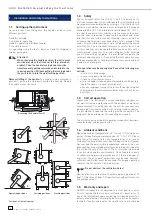
The trigger system of the HMO is
easy to handle by just observing
the HAMEG concept of instrument
operation.
Fig. 6.1: Front panel control area of
the trigger system
There are 4 keys destined for frequently used functions:
–
TYPE:
selects the type of trigger: SLOPE, PULSE, LOGIC,
VIDEO and the B-TRIGGER.
–
SLOPE:
selects the slope polarity.
–
SOURCE:
opens the menu for the selection of the trigger
source.
–
FILTER:
opens the menu for the selected trigger type in
order to select the exact trigger conditions.
Additional keys are provided for the selection of the trigger
modes: (AUTO. NORMAL, SINGLE).
6.1. Trigger modes Auto, Normal, Single
The basic trigger modes are directly selectable with the key
AUTO NORM. In AUTO mode the key will not be lit. If the key is
pushed it will light up red indicating NORMAL mode.
The oscilloscope always presents a signal in AUTO mode and
a signal will automatically yield a stable display if it fulfi lls the
trigger conditions.
In NORMAL mode the signal will be displayed if it fulfi lls the
trigger conditions, if it fails to do so the last stable triggered
display will remain on the screen.
If it is desired to record a signal which fulfi lls the trigger con-
LEVEL
TRIGGER
TRIG’d
SLOPE
AUTO
NORM
TYPE
SOURCE
FILTER
SLOPE
SINGLE
28
C
29
30
33
31
34
35
36
32
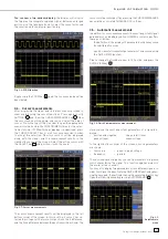
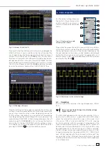
Fig. 6.2: Coupling modes with slope trigger
Fig. 5.2: ZOOM function

