12
Subject to change without notice
A q u i c k i n t r o d u c t i o n
3 A quick introduction
The following chapter is intended to introduce you to the most
important functions and settings of your new HAMEG HMO352x
oscilloscope in order to allow you to use the instrument im-
mediately. The internal calibrator signal output is used as the
signal source, so you will not need any additional instruments
for the fi rst steps.
3.1. Setting up and turning the instrument on
Position the handle so the display will be inclined slightly up-
wards. (See chapter 1.2 for positioning of the handle.) Plug the
power cord into the rear panel connector. The instrument will
be turned on by pushing the red key On/Off
1
on the front panel.
After a few seconds the display appears, and the oscilloscope
is ready for measurements. Now press the key AUTOSET
15
for at least 3 seconds.
CURSOR/MENU
ANALYZE
GENERAL
CURSOR
SELECT
CURSOR
MODE
AUTO
MEASURE
SCROLL
BAR
CURSOR
MEASURE
FFT
QUICK
VIEW
DISPLAY
AUTO
SET
SETUP
HELP
SAVE
RECALL
INTENS
PERSIST
FILE
3
A
5
15 16
8
11
14
9
10
6
7
12
13
4
17
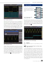
Fig. 3.1: Control panel HMO352x
3.2. Connection of a probe and signal capture
Take one of the probes HZ350 delivered with the instrument,
the ground cable and the probe tip.
STOP
The passive probes should be calibrated before
fi rst use. Please follow the instruction of the probe
manual. Please use the shortest ground connection
possible to the PROBE ADJUST output.
Connect the ground cable to the probe and the tip to the top of
the probe. Now connect the compensation box BNC connector
to the input connector of channel 1 and secure it by turning it
CW until it latches. Connect the ground cable to the left output
jack and hold the tip to the right jack of PROBE ADJUST. The
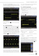
following display should be visible.
Fig. 3.2: Screen display after connection of the probe
On the right hand side of the screen you will see a short menu of
channel 1, the soft keys allow you to select frequently used settings.
Press the top soft key once to change the input coupling to DC.
STOP
The actual settings are marked by underlying blue
fi elds, repeated pressing of the keys will alternate
between the settings.
Fig. 3.3: Screen display after changing to DC coupling
Now press the AUTOSET key
15
once shortly, after a few seconds
the oscilloscope will have automatically selected appropriate
vertical, horizontal time base and trigger settings. You will see
now a square wave signal.
Fig. 3.4: Screen display after Autosetup
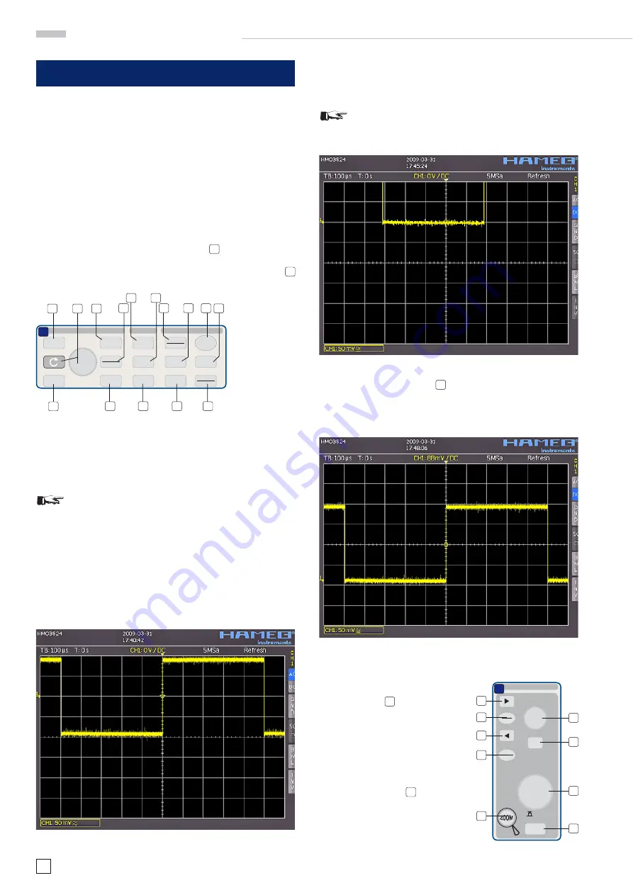
3.3. Display of signal de-
tails
With the knob
43
you can change
the displayed time window: turning
it CCW will slow the time base. The
memory depth of 2 MB per channel
allows you to capture wide time win-
dows with high resolution. Continue
to turn the knob CCW until you read
„TB:5ms“ in the top left corner. Now
press the ZOOM key
40
.
Fig. 3.5: Area of the control panel
containing the ZOOM knob
SCALE
TIME / DIV
X-POSITION
HORIZONTAL
TB/Z
MEM
O
R
Y
MENU
ACQUIRE
RUN
STOP
SET
CLR
37
D
38
37
41
39
42
43
44
40


