16
Subject to change without notice
V e r t i c a l s y s t e m
STOP
The passive probes must be adjusted to the inputs
to which they are connected. See the probe manual
for the adjustment procedure. The PROBE ADJUST
output is only usable for 1:1 and 10:1 probes, for
100:1 or 1000:1 probes special external genera-
tors with a perfect step response have to be used.
Please use the shortest possible ground connec-
tion.
The coupling is selected in the short menu: by just pushing the
appropriate key the coupling is chosen, also the signal may be
inverted. The menu is valid for the activated channel as indicated
by the channel key light up. The channel number will be shown
in the top of the menu. By pushing the respective key of another
channel the menu will transfer to this channel.
4.2. Sensitivity, Y-Positioning, and Offset
The sensitivity of the analog inputs can be selected with the large
knob in the CHANNEL CONTROL section of the front panel in
1-2-5 steps from 1 mV/div to 5 V/div independent of the 50 Ω or
1 MΩ selection. The knob is associated with the channel selected
by pushing the respective key. The sensitivity can be changed
to continuous control by pushing the knob once. The smaller
one of the knobs is used for vertical positioning.
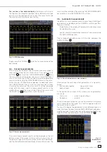
By pushing the MENU key the extended menu is called. On page
2 of this menu a DC offset can be added to the signal. In order
to switch this offset in the respective soft key must be pushed.
The settings window will be backlit in blue, and the activity
indicator next to the general knob will light up; the offset can
now be adjusted with the knob. The offset voltage will be added
to the signal at the vertical amplifi er input offsetting it by that
amount from the zero position. The possible amount of offset
depends on the Volts/div setting chosen. The offset function
being activated will be indicated by two channel markers on
the left of the display, also visible if the menu was closed. One
marker indicates the position, the other the offset (refer to Fig.
4.3). The offset is individually adjustable for each channel.
Each analog channel may also be shifted in time by ±15 ns. This
adjustment is selected in the same menu and according to the
same method as the DC offset; it is used for compensating for
the different signal delays of voltage and current probes and
different cable lengths.
4.3. Bandwidth Limit and Signal Inversion
An analog 20 MHz low pass can be inserted in the signal path
in either the short or extended menu. This will eliminate all
higher frequency interference. The fi lter is activated in the
short menu by pushing the respective soft key; the information
fi eld will be backlit in blue,
BW
will be displayed in the channel
information window.
Signal inversion is available in the short and the extended me-
nus. If it is activated the information fi eld will be backlit in blue,
and there will be a bar above the channel number.
4.4. Probe
attenuation
selection
The HZ350 probes supplied with the instrument will be re-
cognized by the instrument which automatically selects the
appropriate factor. If any other probe without automatic recog-
nition of the attenuation ratio or just a cable is connected to the
instrument, the attenuation factor can be set manually in the
extended menu. This is possible for x 1, x 10, x 100 x 1000 or as
defi ned by the user from x 0.001 to x 1000.
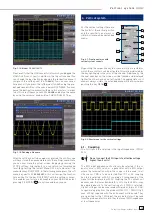
Fig. 4.3: Vertical offset in the extended menu


