3
Subject to change without notice
C o n t e n t s
General information regarding the CE marking
2
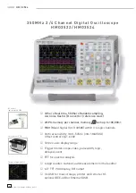
350 MHz Digital Oscilloscope HMO3522 / HMO3524
4
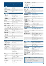
Specifi cations
5
1 Installation and safety instructions
6
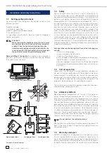
1.1. Setting up the instrument
6
1.2. Safety
6
1.3. Correct
operation
6
1.4. Ambient
conditions
6
1.5. Warranty
and
repair
6
1.6. Maintenance
7
1.7. CAT
I
7
1.8. Mains
voltage
7
2 Familiarize yourself with your new HAMEG
Digital Storage Oscilloscope
8
2.1. Front
view
8
2.2. Control
panel
8
2.3. Screen
9
2.4. Rear
view
9
2.5. Options
9
2.6. General concept of instrument operation
9
2.7. Basic setting and integrated help
10
2.8. Firmware- and help updates
11
3 A quick introduction
12
3.1. Setting up and turning the instrument on
12
3.2. Connection of a probe and signal capture
12
3.3. Display of signal details
12
3.4. Cursor
measurements
13
3.5. Automatic
measurements
13
3.6. Mathematical
functions
14
3.7. Storing
data
14
4 Vertical
system
15
4.1. Coupling
15
4.2. Sensitivity, Y-Positioning, and Offset
16
4.3. Bandwidth Limit and Signal Inversion
16
4.4. Probe
attenuation
selection
16
5 Horizontal System (Time Base)
17
5.1. Capturing modes RUN and STOP
17
5.2. Time
base
adjustments
17
5.3. Capture
modes
17
5.4. ZOOM
function
17
6 Trigger
System
18
6.1. Trigger modes Auto, Normal, Single
18
6.2. Trigger
sources
19
6.3. Slope
trigger
19
6.4. Pulse
trigger
19
6.5. Video
trigger
20
7 Display of signals
20
7.1. Display
settings
20
7.2. Use of the virtual screen area
20
7.3. Signal intensity and persistence functions
21
7.4. XY
display
21
8 Measurements
22
8.1. Cursor
measurements
22
8.2. Auto
measurements
23
8.3. Quickview
measurements
24
9 Analysis
24
9.1. Quick
mathematics
24
9.2. Formula
editor
25
9.3. Frequency
analysis
(FFT)
26
10 Documentation, storing and recalling
27
10.1. Instrument settings
27
10.2. References
28
10.3. Curves
28
10.4. Screen shots
29
10.5. Sets of formulas
29
10.6. Defi nition of the FILE/PRINT key
29
11 Mixed Signal Operation (optional)
30
11.1. Logic trigger
30
11.2. Display functions of the logic channels
30
11.3. Cursor measurements for the logic channels 31
12 Appendix
32


