background image

22

Subject to change without notice

displays the frequency and phase relationships of the signals 
may be derived. The XY function will be activated by pushing the 
XY key in the CHANNEL CONTROL section of the front panel; 
the key will light up, and the screen will be partitioned in a large 
and some small display fi elds: the large display will show the 
XY presentation, the small fi elds will show the sources of the X, 
the Y1, Y2 and Z signals; those signals will be displayed vs. time 
as usual. It is possible to defi ne two signals as the Y signal and 
display this vs. the X signal in order to perform a comparison. 
In order to defi ne which signal should be X, Y1, Y2 or Z, it is ne-
cessary to call the menu by a pushing the XY key a second time. 
In this menu the desired settings may be performed. 

In order to select the Z input setting please push the soft menu 
key next to the menu item 

Z SETTINGS

, this will open the next 

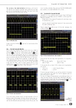
menu level. The Z input allows  control of the intensity of the X-Y 
curve. This intensity may be either set to a desired level or it may 
be dynamically modulated by the amplitudes at the Z input.

Fig. 7.5: Settings for the Z input

In this menu you can fi rst activate the Z input (top menu item 

ON


or 

OFF

, the activated mode will be backlit in blue). In the next 

menu item all channels are offered as inputs, the selection is 
performed with the universal knob and activated by pushing 
the respective menu key next to 

SOURCE Z

. The following menu 

item allows you to defi ne the intensity setting. The menu key will 
toggle between 

Modulation

 and 

On/Off

. If 

Modulation

 is 

selected, the XY signal will be intensity modulated by the amp-
litude at the Z input. The intensity will be proportional to the Z 
input signal amplitude. If 

On/Off

 is selected, all XY points below 

a certain level at the Z input will be shown dark, and all above 
this level will be bright. The level can be set with the universal 
knob after pushing the respective soft menu key. 

Pushing the XY key in the CHANNEL CONTROL section of the 
front panel again will terminate the XY function if it was active. 
If no or another menu should be active, it will be necessary to 
push the XY key twice for terminating the function. 

 8  Measurements

There are two different kinds of measurements on signals: cur-
sor measurements and automatic measurements. All results 
are stored in a buffer memory which is larger than the display 
memory. The QuickView mode delivers all available parameters 
of a signal curve. The integrated hardware counter shows the 
count results on the selected channel.

8.1. Cursor 

measurements

The most frequently used measurement method with an oscil-
loscope is the cursor measurement. The HAMEG concept is 
oriented towards the expected results and thus provides not 
only one or two  but in some modes, three cursors. Cursor 
measurements are controlled by the keys: CURSOR MEASURE, 
CURSOR MODE, and CURSOR SELECT and the universal knob. 
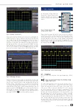
The kind of measurement can be defi ned in the menu which will 
open upon pushing the key CURSOR MEASURE.

Fig. 8.1: Cursor measurements selection menu

As shown above, the selection of the kind of measurement can 
be done by pushing the respective soft menu key and selecting 
the kind of cursor measurement with the universal knob. The 
results will be displayed below the graticule. In order to move 
a cursor, select the desired cursor with the CURSOR SELECT 
key and position the cursor with the universal knob. The kinds of 
measurements are:

VOLTAGE

This mode provides 2 cursors in order to measure 3 different 
voltages. The values V1 and V2 represent the voltages differences 
between the zero base line and the actual positions of the two 
cursors on the selected signal curve. ΔV represents the voltage 
difference between the cursors. 

TIME

This mode provides 2 cursors in order to measure 3 different 
times and an equivalent frequency. The values t1 and t2 represent 
the times between the trigger and the position of the cursors. Δt 
represents the time between the cursors. 

RATIO X

This mode provides 3 cursors in order to measure ratios in X direc-
tion (e.g. a duty cycle) between the fi rst and the second and between 
the fi rst and the third cursors. The values will be presented in 4 
different formats: fl oating point, percent, degrees, radians.

D i s p l a y  o f  s i g n a l s          

Summary of Contents for Hameg HMO3522

Page 1: ...350 MHz Digital Oscilloscope with FFT and mixed signal option HMO3522 3524 Manual English...

Page 2: ...different For measurementoperationthefollowinghintsandconditionsregardingemission and immunity should be observed 1 Data cables For the connection between instrument interfaces and external devices c...

Page 3: ...1 Coupling 15 4 2 Sensitivity Y Positioning and Offset 16 4 3 Bandwidth Limit and Signal Inversion 16 4 4 Probe attenuation selection 16 5 Horizontal System Time Base 17 5 1 Capturing modes RUN and ST...

Page 4: ...mV 5V div into 1M 50 Offset control 0 2 20V 12div x axis display range Trigger modes slope video pulsewidth logic delayed event FFT for spectral analysis 6 digit counter Autoset automeasurement formul...

Page 5: ...tenuation ID HZ350 Dual Interface USB RS 232 HO720 CD Optional accessories HO730 Dual Interface Ethernet USB HO740 Interface IEEE 488 GPIB galvanically isolated HZ46 4RU 19 Rackmount Kit HZ355 Slimlin...

Page 6: ...f visible damage in case loose parts were noticed if it does not function any more after prolonged storage under unfavourable conditions e g like in the open or in moist atmosphere after any improper...

Page 7: ...ring circuits are considered not connected to the mains if a suitable isolation transformer ful lling safety class II is used Measurements on the mains are also possible if suitable probes like curren...

Page 8: ...interface STOP Please note the connectors for the active logic probes HO3508 51 52 are solely for theses probes Connecting anything else could destroy the inputs 2 2 Control panel The controls on the...

Page 9: ...nel actually being displayed these may be selected using the soft keys 3 Below the graticule measurement results of parameters and cursors the settings of the activated vertical channels of the refere...

Page 10: ...e the rst one will follow 2 7 Basic setting and integrated help Basic settings like language for user interface and help mis cellaneous settings and interface settings can be set using the menu which...

Page 11: ...r the date and build information Fig 2 11 Updating menu and information window Now choose which to update the rmware or the help function If both are to be updated it is recommended to rst update the...

Page 12: ...t ground connection possible to the PROBE ADJUST output Connect the ground cable to the probe and the tip to the top of the probe Now connect the compensation box BNC connector to the input connector...

Page 13: ...ner of the screen In this case the V cursor has se lected the voltages at the two cursor positions their difference and the time difference between the positions will be shown The cursors will be swit...

Page 14: ...ne or two prede ned mathematical functions A quick setting of mathematical functions is possible by selecting the menu item at the bottom This mode allows you to select the addition or subtraction of...

Page 15: ...4 1 Front panel area with vertical system controls SCALE VOLTS DIV Y POSITION CHANNEL CONTROL FINE 62 K304 1 1 5 0 1 0 MENU CH1 CH2 CH3 POD1 MATH REF XY CH4 POD2 18 B 19 20 22 23 24 21 25 26 27 By pu...

Page 16: ...ob The offset voltage will be added to the signal at the vertical ampli er input offsetting it by that amount from the zero position The possible amount of offset depends on the Volts div setting chos...

Page 17: ...envelope of the signal will be displayed Average Functions only with repetitive signals The universal knob in the CURSOR MENU section of the front panel is used to set the number of signal periods for...

Page 18: ...tly used functions TYPE selects the type of trigger SLOPE PULSE LOGIC VIDEO and the B TRIGGER SLOPE selects the slope polarity SOURCE opens the menu for the selection of the trigger source FILTER open...

Page 19: ...he trigger such that rst condition A must be met and then another condition B before the trigger will respond refer to Fig 6 3 E g it is possible to de ne a source channel and a level of 120mV on the...

Page 20: ...me available which can be shifted up and down with the universal knob A detailed description will follow in the next chapter There are 3 more menu items on the rst page DOTS ONLY The respective soft m...

Page 21: ...ion to the time elapsed This mode can be selected in the soft menu which will open upon pushing the key INTENS PERSIST the signal intensity can be changed also in this menu Fig 7 2 Menu for setting th...

Page 22: ...will terminate the XY function if it was active If no or another menu should be active it will be necessary to push the XY key twice for terminating the function 8 Measurements There are two different...

Page 23: ...SORMODEopensthemenuitemGLUE TO Thismode can be turned on or off If activated the cursors will glue to the signal i e they will automatically follow all changes of the position and scaling controls and...

Page 24: ...mode offers the following 5 parameters which are directly displayed in the signal Maximum voltage Mean voltage Minimum voltage Rise time Fall time 4 additional parameters will be displayed in the righ...

Page 25: ...the associated menu In Fig 9 4 in formula MA1 a current of 100 A is added to the channel 1 In the menu for entering constants it is possible to choose from the following list of constants executed by...

Page 26: ...beshown top left the information about the Zoom and position between both grids and the information about the FFT display span and center frequency is shown below the larger area One of these displays...

Page 27: ...menu key next to STORE In order to recall stored instrument settings call the main instrument settings menu and select LOAD by pushing the respective soft menu key The data manager will open use the m...

Page 28: ...addition to references the pure A D converter data can be stored however only on external USB sticks not internally The following formats are available Binary format A binary data set may contain byte...

Page 29: ...item is called FORMULARIES selection of this menu item will call a submenu which allows you to move sets of for mulas between the internal memory and the USB stick as well as to import or export such...

Page 30: ...menu eld below by the respective soft key These 6 criteria are available ti t The duration of the bit pattern which will generate the trigger is unequal to the reference time ti t The duration of the...

Page 31: ...his method all channels may be individually positioned and sized If POD was activated and if the MENU key in the Channel Control section of the front panel was pushed the menu for setting the trigger...

Page 32: ...e 15 Fig 4 1 Front panel area with vertical system controls 15 Fig 4 2 Short menu for the vertical settings 15 Fig 4 3 Vertical offset in the extended menu 16 Fig 5 1 Control panel of the horizontal s...

Page 33: ...33 Subject to change without notice A p p e n d i x...

Page 34: ...34 Subject to change without notice Appendix...

Page 35: ...35 Subject to change without notice A p p e n d i x...

Page 36: ...tra e 6 HAMEG Instruments GmbH D 63533 Mainhausen A Rohde Schwarz Company Tel 49 0 61 82 800 0 DQS Certi cation DIN EN ISO 9001 2000 Fax 49 0 61 82 800 100 Reg Nr 071040 QM sales hameg com Oscilloscop...

Reviews: