15
Subject to change without notice
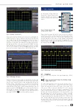
Fig. 3.14: Menu
SCREENSHOTS
Please verify that the USB connector into which you plugged the
USB stick (front or rear) is written in the top soft menue (You
can change the destination by opening the respective menu if
you press the softkey next to
STORAGE
). You can now save a
Screenshot if you press the softkey next to SAVE using the pre-
defi ned name written in the menu below FILE NAME. You may
name the destination memory with up to 8 characters; in order
to do this select the menu item
FILE NAME
and defi ne the name
by using the universal knob and the CURSOR SELECT key.
Fig. 3.15: Defi ning a fi le name
After the soft key next to
Accept
was pressed the oscilloscope
will have stored the name and return to the settings menu. Here
you can now store the actual screen display by pressing the
STORE soft key. Alternatively, you can return to a lower menu
level (by pressing the lowest Menu OFF key) and select the
menu item key FILE/PRINT. In the following menu press the soft
menu key next to
SCREENSHOTS
: this will assign the function
Screen Shot to the key FILE/PRINT with the settings chosen.
This enables you to store a bit map fi le on your USB stick by just
pressing FILE/PRINT
17
at any time and in any menu.
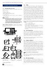
4 Vertical system
For the vertical settings there are
the knobs for the vertical position
and the sensitivity, an always vi-
sible short menu and an extended
menu.
Fig. 4.1: Front panel area with
vertical system controls
SCALE
VOLTS / DIV
Y-POSITION
CHANNEL CONTROL
FINE
62-K304-1
15
0 -
1
.0
MENU
CH1
CH2
CH3
POD1
MATH
REF
X Y
CH4
POD2
18
B
19
20
22
23
24
21
25
26
27
By pushing the respective key the channel will be selected for
which these controls will be activated, this will be indicated by
the key lighting up in the color of the channel. Additionally, the
channel number on the screen will be framed and displayed
lighter than the channels not activated. The appropriate short
menu is always visible, the extended menu will be shown upon
pushing the key MENU
21
.
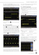
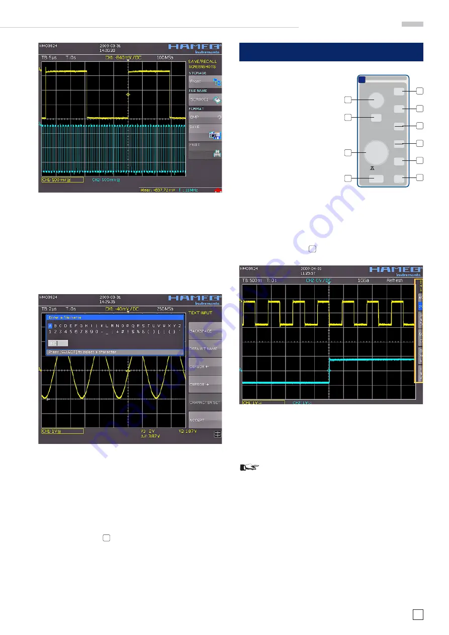
Fig. 4.2: Short menu for the vertical settings
4.1. Coupling
The fi rst item to be selected is the input impedance: 1MΩ or
50 Ω.
STOP
Do not connect the 50 Ω inputs to effective voltage
higher than 5 volts!
The 50 Ω input impedance should only be selected if the si-
gnal source is 50 Ω, such as a generator with a 50 Ω output
where the termination within the scope is to be used. In all
other cases 1 MΩ is to be selected. Next DC or AC coupling
has to be selected: with DC coupling all components of the
signal will be displayed, with AC coupling the DC content will
be removed, the lower bandwidth is 2 Hz. Up to 250 V
rms
may
be applied directly to the vertical inputs if 1 MΩ is selected.
Higher voltages can be measured with probes (up to 40 KVp).
For general applications the probes HZ350 (10:1, 10 MΩ II 12 pF,
max. 400 Vp) supplied with the instrument will be used. They
are specifi ed for the 1 MΩ input; the probe factor will be read
from the probe and factored in; they feature a 10 MΩ impedance
at low frequencies.
V e r t i c a l s y s t e m


