4.Service Tables
57
7
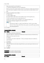
Printer Switch 01 (SP No. 1-103-002)
No Function
Comments
0-
2
Not used
Do not change the settings.
3-
4
Maximum print width used in the setup
protocol
These bits are only effective when bit 7 of printer switch 01 is "1".
Bit 4
Bit 3
Setting
0
0
Not used
0
1
A3
1
0
B4
1
1
A4
5-
6
Not used
Do not change the settings.
7
Received message width restriction in the
protocol signal to the sender
0: Disabled
1: Enabled
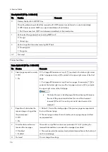
0: The machine informs the transmitting machine of the print width
depending on the paper size available from the paper feed
stations.
Refer to the table on the next page for how the machine chooses
the paper width used in the setup protocol (NSF/DIS).
1: The machine informs the transmitting machine of the fixed paper
width which is specified by bits 3 and 4 above.
Relationship between available paper sizes and printer width used in the setup protocol
Available Paper Size
Printer width used in the Protocol (NSF/DIS)
A4 or 8.5" x 11"
297 mm width
B5
256 mm width
A5 or 8.5" x 5.5"
216 mm width
No paper available (Paper end)
216 mm width
Printer Switch 02 (SP No. 1-103-003)
No Function
Comments
0* 1st paper feed station
usage for fax printing
0: Enabled
1: Disabled
0: The paper feed station can be used to print fax messages and reports.
1: The specified paper feed station will not be used for printing fax messages and
reports.
Do not disable usage for a paper feed station which has been specified
by User Parameter Switch 0F (15), or which is used for the Specified
Cassette Selection feature.
1* 2nd paper feed station
usage for fax printing
0: Enabled
Summary of Contents for M0A0
Page 2: ......
Page 10: ...8 ...
Page 12: ......
Page 34: ...2 Installation 22 9 Enter the password 10 Press OK 11 Enter the password again ...
Page 85: ...2 Installation 73 ...
Page 189: ...4 Replacement and Adjustment 177 ...
Page 203: ...5 System Maintenance 191 SP Mode Tables See Appendices ...
Page 229: ...5 System Maintenance 217 LDAP authorization information ...
Page 344: ...7 Detailed Descriptions 332 side guides from side to side ...
Page 358: ...7 Detailed Descriptions 346 ...
Page 368: ......
Page 558: ......
Page 574: ...1 Replacement and Adjustment 16 7 LCD A 4 8 Microphone A cushioning 1 ...
Page 622: ......
Page 624: ... A Short Edge Feed SEF B Long Edge Feed LEF ...
Page 626: ......
Page 632: ...1 Installation 6 ...
Page 752: ...5 Detailed Section Descriptions 126 Report Sample ...
Page 758: ...6 Specifications 132 Fax Unit Configuration Component No Remarks FCU 1 Speaker 2 ...
Page 760: ......
Page 762: ......
Page 776: ...2 Replacement and Adjustment 14 4 Detach the paper size switch from the bracket A Hook x2 ...


