7.Detailed Descriptions
325
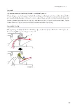
The transfer current is adjusted in accordance with the paper tray (paper feed unit, bypass tray, and duplex tray),
paper size, paper type, and print number of sheets.
You can adjust these levels (SP2-301 T bias control).
Increasing the transfer current may produce ghost images–part of the image near the leading edge
reappears on another part of the page.
Increasing the transfer current might damage the OPC drum.
Paper Separation
The paper separates from the OPC drum because of the curvature of the OPC drum and because of the grounded
discharge plate downstream of the transfer roller. Irregularities in the toner image at the time of separation are
prevented by an electric field.
Transfer Roller Cleaning
Toner may transfer to the roller surface following a paper jam or if the paper is smaller than the image. Periodic
cleaning of the roller is required to prevent this toner from migrating back to the rear of new printouts.
The machine cleans the roller at the following times:
After initial power on.
After clearing of a copy jam
At the end of a job
The PSU first supplies a negative cleaning current (about -4 A) to the transfer roller, causing negatively charged toner
on the roller to move back to the drum. It then applies a positive cleaning current (+5 A) to the roller, causing any
positively charged toner to migrate back to the drum.
Related SPs
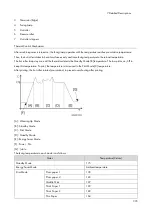
2-301-xxx [T bias Control]:
Use these SPs to adjust the power output and power coefficient used to transfer the toner image from drum to
paper. Four separate voltages are applied: before the leading edge, at the leading edge of the paper, across the
image area, and at the trailing edge of the paper.
Summary of Contents for M0A0
Page 2: ......
Page 10: ...8 ...
Page 12: ......
Page 34: ...2 Installation 22 9 Enter the password 10 Press OK 11 Enter the password again ...
Page 85: ...2 Installation 73 ...
Page 189: ...4 Replacement and Adjustment 177 ...
Page 203: ...5 System Maintenance 191 SP Mode Tables See Appendices ...
Page 229: ...5 System Maintenance 217 LDAP authorization information ...
Page 344: ...7 Detailed Descriptions 332 side guides from side to side ...
Page 358: ...7 Detailed Descriptions 346 ...
Page 368: ......
Page 558: ......
Page 574: ...1 Replacement and Adjustment 16 7 LCD A 4 8 Microphone A cushioning 1 ...
Page 622: ......
Page 624: ... A Short Edge Feed SEF B Long Edge Feed LEF ...
Page 626: ......
Page 632: ...1 Installation 6 ...
Page 752: ...5 Detailed Section Descriptions 126 Report Sample ...
Page 758: ...6 Specifications 132 Fax Unit Configuration Component No Remarks FCU 1 Speaker 2 ...
Page 760: ......
Page 762: ......
Page 776: ...2 Replacement and Adjustment 14 4 Detach the paper size switch from the bracket A Hook x2 ...

