6.Troubleshooting
253
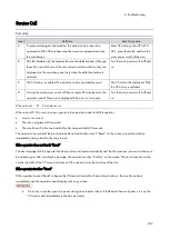
SC No.
Level
Error Name/Error Condition/Major Cause/Solution
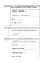
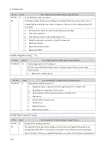
Clear the SP: fusing SC.
Check the connector connection.
Replace the fusing (End) thermistor.
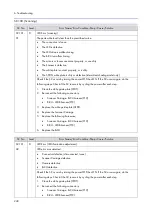
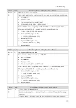
SC No. Level
Error Name/Error Condition/Major Cause/Solution
SC553-
01
SC553-
02
A
Fusing (End) thermistor high-temperature detected (software)
(553-01)
In a condition of 235 degrees C or higher temperature, the temperature has increased more than
10 degrees C per 1 second, the heater has continuously reached 100% (maximum) duty, and
the center thermistor has detected the failure to reach the target temperature by 11 degrees C.
(553-02)
The temperature is detected to stay at 250 degrees C or higher for one second.
Failed fusing (end) thermistor
Clear the SP: fusing SC.
Replace the fusing (end) thermistor.
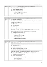
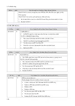
SC No.
Level
Error Name/Error Condition/Major Cause/Solution
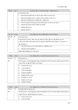
SC554-
00
A
Fusing (End) thermistor high-temperature detected (hardware)
The hardware high-temperature error sensor flag is detected (250 degrees C or higher).
Damaged triac (shorted)
Failed engine control board
Failed fusing thermopile
Failed fusing thermistor
Abnormal fusing control software behavior
The PWM signal is continuously supplied from the IH inverter (due to a software or
temperature sensor error).
Clear the SP: fusing SC.
Replace the PSU.
Replace the Engine Board.
Replace the fusing thermopile.
Replace the Fusing Unit.
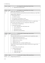
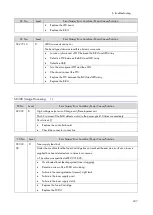
SC No.
Level
Error Name/Error Condition/Major Cause/Solution
SC557-00
C
Zero-crossing frequency exceeded
The number of zero-crossing interrupts exceeds a certain value in 500 ms.
The frequency of the commercial power supply line is unstable or noise occurs.
None
Summary of Contents for M0A0
Page 2: ......
Page 10: ...8 ...
Page 12: ......
Page 34: ...2 Installation 22 9 Enter the password 10 Press OK 11 Enter the password again ...
Page 85: ...2 Installation 73 ...
Page 189: ...4 Replacement and Adjustment 177 ...
Page 203: ...5 System Maintenance 191 SP Mode Tables See Appendices ...
Page 229: ...5 System Maintenance 217 LDAP authorization information ...
Page 344: ...7 Detailed Descriptions 332 side guides from side to side ...
Page 358: ...7 Detailed Descriptions 346 ...
Page 368: ......
Page 558: ......
Page 574: ...1 Replacement and Adjustment 16 7 LCD A 4 8 Microphone A cushioning 1 ...
Page 622: ......
Page 624: ... A Short Edge Feed SEF B Long Edge Feed LEF ...
Page 626: ......
Page 632: ...1 Installation 6 ...
Page 752: ...5 Detailed Section Descriptions 126 Report Sample ...
Page 758: ...6 Specifications 132 Fax Unit Configuration Component No Remarks FCU 1 Speaker 2 ...
Page 760: ......
Page 762: ......
Page 776: ...2 Replacement and Adjustment 14 4 Detach the paper size switch from the bracket A Hook x2 ...

