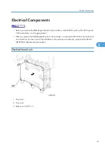
• Keep NVRAMs away from objects that can cause static electricity. The data in NVRAMs can be
corrupted by static electricity.
• Make sure the NVRAM is correctly installed on the board. A half-disk is engraved on one side
of the NVRAM, and a guide mark is on one side of the NVRAM slot. When you install the
NVRAM, the half-disk and the guide mark must be on the same side.
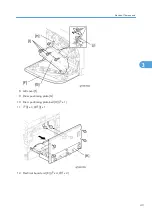
LCD Panel
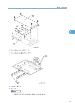
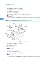
1. LCD panel [A] (
x 1)
NVRAM Replacement Procedure
Make sure that you have the SMC report (factory settings) before beginning the following procedure.
NVRAM on the EGB (Engine Board)
For this procedure, you must know the device number and the destination code (
*
step 8).
1. Start the SP mode.
2. Use SP5-990 to print out the SMC reports (“SP Mode Data” and “Logging Data”) if possible.
3. Turn off the main power switch and unplug the power cord.
Electrical Components
49
3
Summary of Contents for G-P3
Page 1: ...Model G P3 Machine Code G190 SERVICE MANUAL January 2008 Subject to change...
Page 11: ...10...
Page 77: ...11 Harness guide C x 2 12 Drive unit D x 6 x 16 3 Replacement and Adjustment 76 3...
Page 91: ...3 Replacement and Adjustment 90 3...
Page 137: ...LEDs No LEDs are used for this model except for the Network Interface 4 Troubleshooting 136 4...
Page 337: ...5 Service Tables 336 5...
Page 411: ...MEMO 410...
Page 412: ...MEMO 411...
Page 413: ...MEMO 412...


