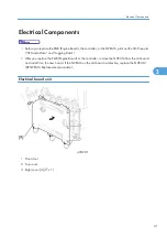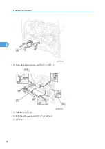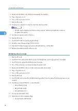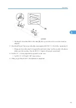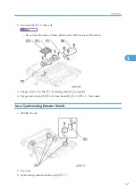
1. Electrical board unit (
*
Electrical board unit)
2. PSU board (
*
PSU (Power Supply Unit) Board)
3. Electrical board unit frame [A] (
x 4)
4. High voltage terminal plate [B] (
x 1)
5. High voltage power supply board 1 [C] (
x 4,
x 4, stand offs x 2).
• Make sure that each high voltage terminal is connected securely after you replace this board.
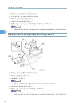
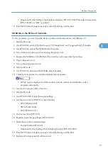
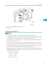
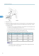
EGB (Engine Board) and High Voltage Power Supply Board 2
1. Electrical board unit (
*
Electrical board unit)
2. EGB shield [A] (
x 3,
x 1)
3. EGB [B] (
x 4,
x 4)
• Remove the NVRAM from the old board. Then install it on the new board.
4. High voltage terminal plate [C] (
x 1)
5. High voltage power supply board 2 [D] (
x 3,
x 2)
• Make sure that each high voltage terminal is connected securely after you replace this board.
3. Replacement and Adjustment
48
3
Summary of Contents for G-P3
Page 1: ...Model G P3 Machine Code G190 SERVICE MANUAL January 2008 Subject to change...
Page 11: ...10...
Page 77: ...11 Harness guide C x 2 12 Drive unit D x 6 x 16 3 Replacement and Adjustment 76 3...
Page 91: ...3 Replacement and Adjustment 90 3...
Page 137: ...LEDs No LEDs are used for this model except for the Network Interface 4 Troubleshooting 136 4...
Page 337: ...5 Service Tables 336 5...
Page 411: ...MEMO 410...
Page 412: ...MEMO 411...
Page 413: ...MEMO 412...


