Preparing for Use
R&S
®
QAR
18
User Manual 1178.7200.02 ─ 04
A = Drill hole location for R&S
QAR
B = Drill hole location for DUT mounting table
Whenever you lift, move or carry the R&S
QAR, use the handles on its back side.
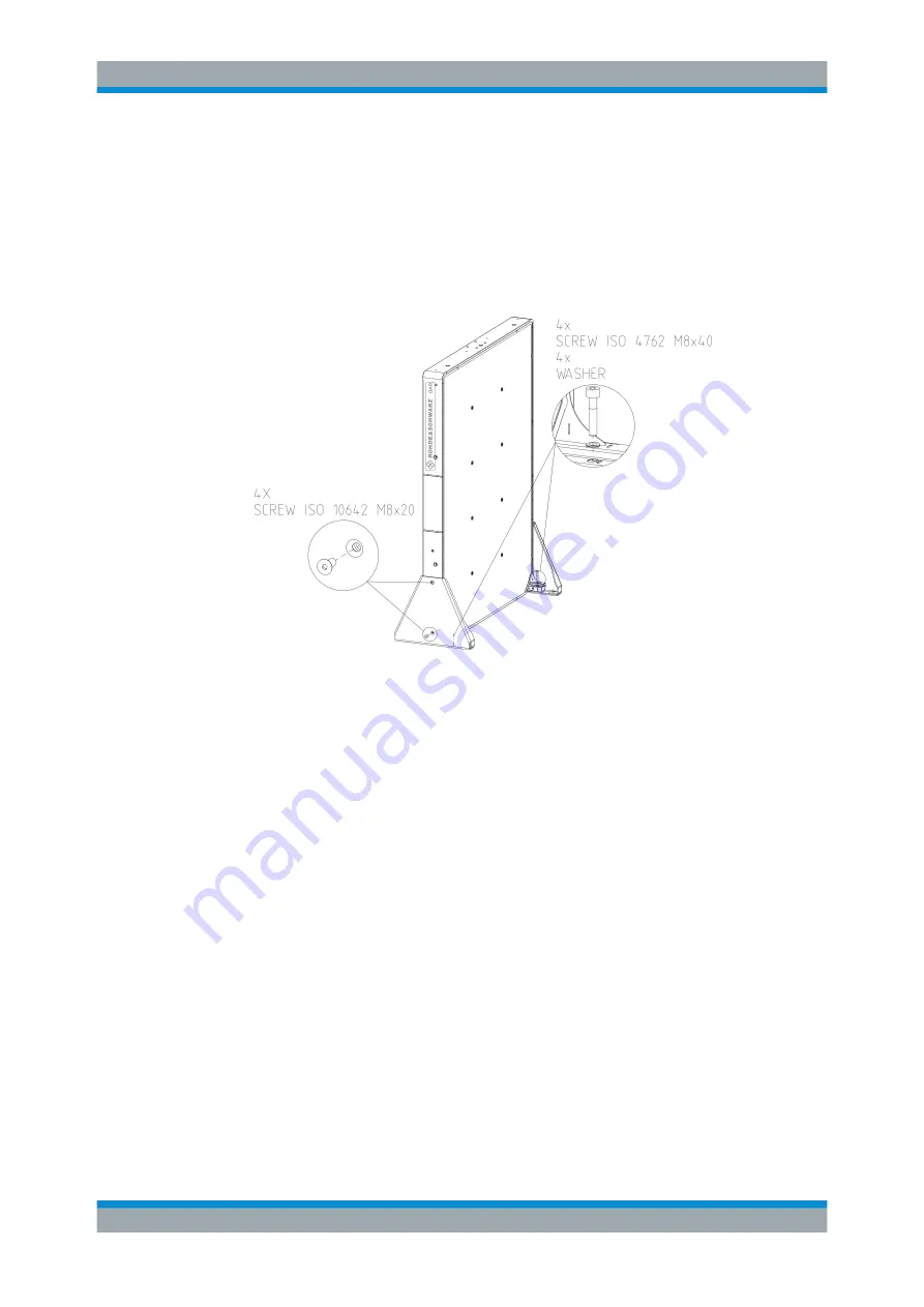
2. Screw the two supports to the side of the R&S
QAR with two socket head screws
(ISO 10642 M8x20, Allen wrench size 5) on each side of the R&S
).
Figure 4-2: R&S
QAR installation, including support installation
3. Screw the two supports to the R&S
QAR with the socket head screws (ISO 4762
M8x40, Allen wrench size 6) on each side of the R&S
Installing the R&S
QAR


