background image

RAINBOW ROBOTICS 

RB SERIES _ USER MANUAL 


© RAINBOW ROBOTICS Inc. All rights reserved. 


338 

8.2


ROBOT


STATUS


CHECK 

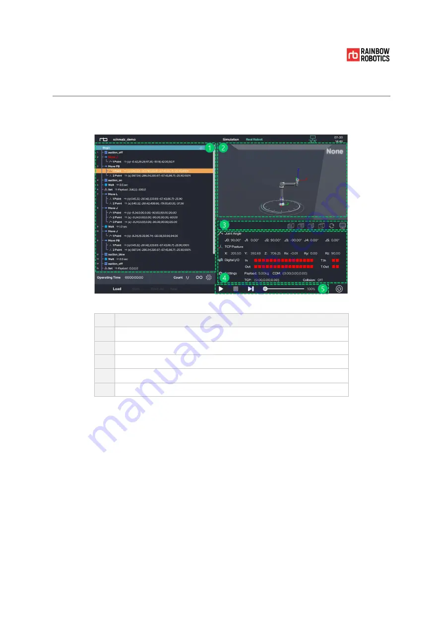
The robot’s current status is shown in the ‘Play’ screen during operation. 


Description 


Program flow tree 


3D viewer 


3D view angle changer 


System information, system variable monitor 


Play / Pause / Stop / Velocity slide bar 

Summary of Contents for RB Series

Page 1: ...RAINBOw English RB SERIES USER MANUAL V 3 9 1 Update 2021 09...

Page 2: ...RAINBOW ROBOTICS RB SERIES _ USER MANUAL RAINBOW ROBOTICS Inc All rights reserved 2...

Page 3: ...E 21 1 8 MAXIMUM LOAD CAPACITY 22 CHAPTER 2 SAFETY PRECAUTIONS 23 2 1 SAFETY INDICATIONS 23 2 2 GENERAL SAFETY WARNING PRECAUTIONS 24 2 3 USAGE FUNCTIONALITY 27 2 4 POTENTIAL SAFETY ISSUES 28 2 5 LIAB...

Page 4: ...4 5 TOOL CONNECTION 55 4 6 CABLE CONNECTION 60 4 7 ROBOT CONTROL BOX I O OVERVIEW 62 4 8 SAFETY INPUT CONFIGURATION 63 4 9 GENERAL PURPOSE DIGITAL I O CONFIGURATION 65 4 10 GENERAL PURPOSE ANALOG I O...

Page 5: ...338 8 3 TROUBLESHOOTING WHILE OPERATING 339 CHAPTER 9 SETUP 343 9 1 SET UP COBOT 343 9 2 SET UP TOOL 344 9 3 SET UP SYSTEM 345 9 4 SET UP LOG 346 9 5 SET UP UTILITY 347 9 6 SET UP SERIAL 348 9 7 SET...

Page 6: ...ENDIX D 1 CONTROL BOX DIGITAL INPUT 375 APPENDIX D 2 CONTROL BOX DIGITAL OUTPUT 380 APPENDIX D 3 TOOL FLANGE DIGITAL INPUT 382 APPENDIX D 4 TOOL FLANGE DIGITAL OUTPUT 385 APPENDIX E EXTERNAL SCRIPT CO...

Page 7: ...ainbow Robotics Inc owns the copyright and intellectual property rights on all contents and designs of this manual Therefore the use duplication and re distribution of Rainbow Robotics Inc properties...

Page 8: ...afety devices The RB series provide robotic solutions to increase productivity for your business Intuitive usability It is easy to set up and operate an RB robot unit Experts and non experts alike can...

Page 9: ...arious types of tools Control Box The Control Box controls the movement of the robot arm based on user programs contained on the Teach pendant tablet PC Digital and analog input output ports are avail...

Page 10: ...Interface 1 EA Power cable 1 EA Cable between Robot Arm Control Box 1 EA Optional Tablet PC Tablet cover USB cable 1 EA Other User Manual Electronic Document 1 EA Please use the 5 meter long power ca...

Page 11: ...RB SERIES _ USER MANUAL RAINBOW ROBOTICS Inc All rights reserved 11 1 3 ROBOT ARM RB series Joint Description No Name Base Base Joint Shoulder Joint Elbow Joint Wrist 1 Joint Wrist 2 Joint Wrist 3 Jo...

Page 12: ...B series Component Description No Name Description Teaching Button Button for direct teaching Tool Flange Part for mounting tool or gripper Tool I O I O ports to control tool or gripper Base Part for...

Page 13: ...RAINBOW ROBOTICS RB SERIES _ USER MANUAL RAINBOW ROBOTICS Inc All rights reserved 13 Dimensions RB5 850E RB5 850EA1 A2 RB3 1200E RB3 1200EA1 A2...

Page 14: ...RAINBOW ROBOTICS RB SERIES _ USER MANUAL RAINBOW ROBOTICS Inc All rights reserved 14 Dimensions RB10 1300E RB10 1300EA1 A2...

Page 15: ...IES _ USER MANUAL RAINBOW ROBOTICS Inc All rights reserved 15 Configuration of the embedded Pneumatic tubing Electric line in RB5 850EA RB3 1200EA and RB10 1300EA Embedded pneumatic tubing connection...

Page 16: ...owing table please refer to the picture above for use Model Name Pneumatic Lines Wire Lines RB5 850EA1 MAX 4EA 4 Pneumatic Tube None RB5 850EA2 MAX 5EA 4 Pneumatic Tube 12 Pin AWG28 RB3 1200EA1 MAX 4E...

Page 17: ...W ROBOTICS RB SERIES _ USER MANUAL RAINBOW ROBOTICS Inc All rights reserved 17 Warning 1 For pneumatic electric wire passing models if passing air or power over the defined standard hardware may be da...

Page 18: ...L BOX The front and lower inner sections of the control box are illustrated in the diagram below Stand type control box No Name AC Power Socket AC POWER AC Power Switch AC SWITCH Connector for Robot A...

Page 19: ...OPTIONAL The teaching pendant tablet PC is an optional accessory It MUST be purchased separately For stand type control box Purchasing the tablet PC is not required The App to operate the RB series ca...

Page 20: ...RAINBOW ROBOTICS Inc All rights reserved 20 1 6 JOINT LIMIT An RB robot unit consists of six joints The axes of rotation and joint limits are illustrated in the following section Joint Range J 1 360...

Page 21: ...below represents the kinematic singular area This means that any motion programmed in the inertial coordinate system e g programming a motion using the Move L command may not work properly The robot...

Page 22: ...W ROBOTICS Inc All rights reserved 22 1 8 MAXIMUM LOAD CAPACITY The maximum payload of the robot arm depends on the distance between the Tool flange and the center of mass of the payload The maximum p...

Page 23: ...his manual Danger Failure to follow instructions marked with this symbol may result in severe harm which could result in serious injury or death Failure to follow the instructions with this symbol may...

Page 24: ...get caught in the joints of the robot 4 Never operate a broken or faulty robot 5 If a fatal error occurs in the software immediately hit the emergency switch to stop the robot and then contact your s...

Page 25: ...aching function input the relevant information tool length weight center of gravity etc accurately Not entering the accurate relevant specifications will cause malfunctions when using the direct teach...

Page 26: ...a warning label to the spot where there is a danger of electric shock from the electric device 2 Do not tear damage or remove the cover Be careful when handling parts or devices with a label attached...

Page 27: ...fter performing the risk evaluation for the whole system The use of the robot in any of the following applications and environments is considered improper use and the manufacturer is not liable for an...

Page 28: ...ger is caught between the gears etc Injury puncture deep cuts by sharp edges or edges of the tool Injury puncture deep cuts falling object caused by objects located near the robot Injury that can occu...

Page 29: ...h the robot arm is applied must be designed and installed to meet safety requirements stipulated in the regulations and laws of the country where the system is installed The operator or installer of t...

Page 30: ...the robot incurred during shipment or transportation are excluded from the warranty Warning 1 Be careful not to damage the product during transportation Damages incurred during transportation will voi...

Page 31: ...p button the user will stop commands from being sent by the robot control box and terminate any motion The section below describes how the Emergency Stop button for stand type control box works Emerge...

Page 32: ...move the robot arm by forcing the joints into a different configuration forced back driving To perform forced back driving the user must push or firmly pull the robot arm Make sure that the robot is n...

Page 33: ...RB SERIES _ USER MANUAL RAINBOW ROBOTICS Inc All rights reserved 33 2 9 SAFETY CONTROLLER The Safety Control System of Rainbow Robotics RB5 850E Series RB3 1200E Series RB10 1300E Series follows ISO...

Page 34: ...nvironment are the key tasks of risk assessment The safety related functions of the collaborative robot can be configured in the safety configuration menu The menu provides the following functions I O...

Page 35: ...overlapping wiring of additional safety devices refer to Section 5 of this chapter 4 System integrators and operators must be informed that there is a safety monitoring function that the robot perform...

Page 36: ...and the control panel must be shut off 3 When installing an additional safety device measures must be taken to ensure that there is no problem when using it mechanically For example when using a light...

Page 37: ...e the power of the robot is shut off it is necessary to restart it when using it again after removing the danger 2 SS2 All the joints of the robot are decelerated to the maximum stop and then enter th...

Page 38: ...LS Safely Limited Speed PL d Category 3 SF 7 SLA Safely Limited Acceleration PL d Category 3 SF 8 SLI Safely Limited Increment PL d Category 3 SF 9 SLT Safely Limited Torque PL d Category 3 SF 10 RPL...

Page 39: ...candidates our system uses SS2 t SOS Safe Operating Stop This function prevents the motor from deviating more than a defined amount from the stopped position The PDS SR provides energy to the motor to...

Page 40: ...orts of the Control Box are activated Those ports are provided for users to connect their own protective devices The stop mode is the SF 2 HSS Hard Safeguard Stop This function activates the stop mode...

Page 41: ...assessment The safety dedicated contact terminal consists of 16 ports This terminal is a redundancy dedicated contact input terminal The additional ports can be equipped with 4 equipment The robot is...

Page 42: ...essment Protective stop devices must be used according to 5 3 8 3 of ISO 10218 2 Protection stops occurring through PRS are designated as stop category 1 HSS This port is used to connect one or more p...

Page 43: ...emergency the robot must be stopped immediately by pressing the emergency stop switch on the top of the pendant Caution Caution 1 The emergency stop switch is designated as stop category 1 2 The emer...

Page 44: ...ic mode you must access it through a password Caution Caution 1 The password for entering automatic mode is not set at the time of shipment Set up and use a password so that no one else can access it...

Page 45: ...simulation and the robot can be driven by the verified program by converting it to a real state At this time the robot is performing pre set safety functions and the user can monitor the status of the...

Page 46: ...bot in a safe state for a long time it must be used in the following conditions environment Maximum allowable operating temperature 50 C Maximum permissible storage temperature 60 C Minimum allowable...

Page 47: ...properly 1 Month Cable Check the condition of the connection cable between the pendant and the control box 1 Month Control Box Interface Check whether the EMO port to which the safety device is connec...

Page 48: ...drive the RB series The information of the LED indicating the operation status of the board is as follows Connector information connected to the board is as follows 48V LED 12V LED Safety Status LED S...

Page 49: ...c programmable electronic safety related systems Part 4 Definitions and abbreviations IEC 61508 5 2010 Functional safety of electrical electronic programmable electronic safety related system Part 5 E...

Page 50: ...electrical power drive systems Part 5 1 Safety requirements Electrical thermal and energy IEC 61800 5 2 2016 Adjustable speed electrical power drive systems Part 5 2 Safety requirements Functional IE...

Page 51: ...0218 2 and installers must comply with the relevant requirements of international standards such as ISO TS 15066 and national laws The manufacturer is not liable for any accidents caused by risks that...

Page 52: ...the following conditions are met for the installation location Building with seismic design No leakage No flammable or explosive material Constant temperature and humidity Limited dust inflow Caution...

Page 53: ...izontal surface e g table a wall the ceiling or any other angle It can also be installed on the fixed post Fixed post is not included in the product However the user must set the angle of installation...

Page 54: ...ithstand the combined weight of the robot and the load generated by the robot 3 Make sure that the contacting surface on the robot arm is completely in contact with the surface that it is mounted upon...

Page 55: ...Tool flange Tools and M6 bolts are not included in the product The connection methods may vary between tools Contact the tool manufacturer for further details After fixing the tool to the Tool flange...

Page 56: ...e AWG22 3 0 12 24 VCC 0 12 24 VCC Red AWG22 4 Ground Ground Black AWG22 5 Digital Input A Digital Input A White AWG26 6 Digital Input B Digital Input B Blue AWG26 7 Analog Input A Digital Input C Whit...

Page 57: ...Max Unit Voltage when opened 0 24 V Current through GND 0 2000 mA The image shown below illustrates how to turn on off a load with 12V or 24V The voltage level can be specified in the Tool Out TO0 bl...

Page 58: ...ital input for a simple switch The tool analog input measures the voltage in a non differential manner The measurement categories are as follows Min Nominal Max Unit Input Voltage 0 10 V Resolution 12...

Page 59: ...ensor to GND ground works the same as the non differential light sensor Caution 1 For further details regarding technical specification and wire connection refer to Appendix D 2 The cross sectional vi...

Page 60: ...le Connect the female connector to the robot arm and the male connector to the control box Be sure to check whether pins in the connector are bent or not Connecting Part for Robot Arm cable Connecting...

Page 61: ..._ USER MANUAL RAINBOW ROBOTICS Inc All rights reserved 61 Caution 1 Do not unplug the robot cable power cable or teaching pendant while the robot is activated 2 For using AC power the peripherals sho...

Page 62: ...ower and digital I O of the control box are as follows All digital I O are compliant with the IEC 61131 2 standard IEC 61131 2 IEC standard for programmable controllers Port Parameter Min Type Max Uni...

Page 63: ...ignal to a PLC other than a safety PLC Failure to follow these warnings could result in unsafe operation resulting in serious injury or casualty The safety signal and general I O signal must be separa...

Page 64: ...Input Option Connect the active device input interface using the 3 position switch When the position activation switch is in the operating position middle position the robot starts moving If the 3 po...

Page 65: ...with the corresponding equipment The universal digital I O can be used to configure devices such as relays or PLC systems In this configuration the output is always LOW unless the program is running T...

Page 66: ...on with other system or PLC If another system provides PNP and uses a common ground the digital I O can be configured to communicate with the other system Its connection is shown in the figure below W...

Page 67: ...the same GND Analog I O is not isolated from the robot control box Use shielded or twisted pair cable Connect to the GND shield on the Power J12 terminal Port Parameter Min Type Max Unit Voltage mode...

Page 68: ...d by the control box as analog input LCD Status Display 1 Display Box 1 Displays information about system status Please Wait the main PC in the control box is booting up Normal Operation the main PC i...

Page 69: ...ol box to apply AC power Press the main power switch at the top of the control box to turn on the main power Please Wait is displayed in the LCD screen of the control box This indicates that the contr...

Page 70: ...aching pendant and cover are provided To turn on the teaching pendant press the power button on the top left corner For stand type control box Caution 1 Make sure that the teaching pendant is connecte...

Page 71: ..._ USER MANUAL RAINBOW ROBOTICS Inc All rights reserved 71 CHAPTER 6 SOFTWARE OVERVIEW 6 1 UI STRUCTURE The UI User Interface program is divided into three screens as follows Each section allows the us...

Page 72: ...72 6 2 STARTUP SCREEN DISPLAY Intro The image below shows the Startup screen The Startup screen will occur while the application loading is processing Login Factory Default login password 0000 To set...

Page 73: ...AY The UI has three main menus Make for programming robot motion and tasks Play for running motion and tasks pre programmed in the Make menu Setup for setting up parameters In the main screen users ca...

Page 74: ...ed 74 Power Off When the power button bottom right is pressed the power off dialog will pop up If the user presses the UI Shutdown button the application closes If the robot is activated and Tablet is...

Page 75: ...s at the right Moving the robot by one of these icons will also be referred to as jogging Editing the teaching program requires the use of icons at the left Left Icons Copy Paste Save Delete Add Comme...

Page 76: ...a teaching program The Play screen only allows for physical movement of the robot unlike Make that allows for simulation A program loaded into the Play screen will repeat the number of times specified...

Page 77: ...SETUP Setup The Setup screen allows the user to see change the robot s default values such as sensitivity for collision detection configuration of the robot installation range of workspace tool setti...

Page 78: ...d coordinate system selectable Joint Jog can change the angle of each joint Button to switch to Simulation or Real mode Real mode must be selected to drive the real robot arm Can import saved projects...

Page 79: ...eserved 79 Teaching programming RB s motion by means of moving the robot by hand TCP Tool Center Point The point defined for the tool center point within the robot s base coordinate system It may also...

Page 80: ...RAINBOW ROBOTICS RB SERIES _ USER MANUAL RAINBOW ROBOTICS Inc All rights reserved 80 Program only Mode...

Page 81: ...and MoveITPL are advanced motions using MoveJ or MoveL This icon is a sub item of Move It sets the target values of motion In MoveJ and MoveJB a desired joint angle value can be set In MoveL MoveLB Mo...

Page 82: ...becomes true This icon will force quit a loop It is used as a sub item of Repeat This icon ends the program It is typically used with a conditional statement to force an end to the motion program in...

Page 83: ...con runs a specific command or program only for one time at the beginning of a program This icon runs a command or program in parallel with the main program Note that motion commands cannot be used in...

Page 84: ...to generate 0V 12V or 24V This icon is used when a gripper manufactured in third party company is attached at the robot Built in functions enable the gripper to be quickly installed and used This icon...

Page 85: ...variables single variables arrays point variables etc to be declared and observed in real time while the program is running Variables declared in the Monitor function can be viewed by clicking the mon...

Page 86: ...automatically given the force control function This feature enables setting macro functions for arc welding It is a dedicated function that binds functions which can be implemented through the normal...

Page 87: ...global ROM by entering it The value can be changed ignored or skipped depending on your situation This function is intended for use in welding applications Detects the movement of the base material a...

Page 88: ...nc All rights reserved 88 This function is used to change the main program to another project This function operates the robot joint and the external axis at the same time This function controls the e...

Page 89: ...our last action usable up to 50 times This function reverses your last Undo usable up to 50 times This function can raise the command one by one This function can lower the command one step at a time...

Page 90: ...es the copied command to a different location This feature pastes the section using the copy or cut command onto the selected location This feature cuts the selected section The section can be placed...

Page 91: ...ection of special features which can view status and set up values such as I O status information of the system user coordinate setting information and current temperature information of the robot Thi...

Page 92: ...button Icon Description This icon is used to move to home screen another page It is located in the top left This icon is used to power off the UI When the tablet PC is connected to the robot the robo...

Page 93: ...Control Box Press the Connect button to link the tablet PC to the robot control box Connect button Will connects the tablet PC to the robot control box Caution 1 Make sure that the control box is tur...

Page 94: ...w shows a display when the tablet PC and control box are being connected Network Connecting flashes yellow when the tablet PC is trying to connect to the control box Network Connected becomes blue whe...

Page 95: ...he robot control system Control button Will initialize the robot arm for operation During initialization the mechanical joint brake is released Unlocking the joints will generate a clicking sound All...

Page 96: ...ect Press the New button at the bottom of the screen to create a new project under an assigned file name The default name of a new project is default Type in a name for the new project and press the S...

Page 97: ...st press and hold the mechanical button located on the Tool flange Pressing this button allows each joint to move freely The red circle in the diagram above indicates the location of the button Warnin...

Page 98: ...ogging Mode 1 TCP Movement in the Cartesian coordinate system with respect to the base global frame Mode 2 TCP Movement in the Cartesian coordinate system with respect to the tool local frame Mode 3 T...

Page 99: ...amount as defined by the user each button click The control method for jogging can be selected via a toggle button located in the top right in the Make screen In Setup Interface a user can specify the...

Page 100: ...RAINBOW ROBOTICS RB SERIES _ USER MANUAL RAINBOW ROBOTICS Inc All rights reserved 100 Jog Mode 1 TCP jog w Global coordinate Jog Mode 2 TCP jog w Local coordinate...

Page 101: ...RAINBOW ROBOTICS RB SERIES _ USER MANUAL RAINBOW ROBOTICS Inc All rights reserved 101 Jog Mode 3 TCP jog w User coordinate Jog Mode 4 Joint jog w joint coordinates...

Page 102: ...robot It is recommended to run simulation mode first for safety reasons before teaching a new motion Real Robot Mode Drives the real robot as displayed on the UI screen Warning 1 Real Robot mode is o...

Page 103: ...for the robot arm and requires points to be defined Point A sub function of Move Defines a destination position for each movement After using the Move and Point functions in an empty program the scrip...

Page 104: ...Movement Commands The Joint Movement Commands generate movement by setting the angular value of each individual joint in degrees MoveJ Move Joint Sets each joint angle to the values contained within...

Page 105: ...rm configuration the arm will move smoothly between each Point without stopping by using the Move L method This method will generate an arc shaped path For each Point the user must specify a Blend Rad...

Page 106: ...e Cartesian coordinate system input is received it is converted into the target joint angle through inverse kinematics and inputted again to MoveJ MoveITPL Move Interpolation Starting from the startin...

Page 107: ...uses the joint angle information of the starting point and the joint angle of the target point The driving speed of other joints is adjusted to the joints that require the most driving time MoveL is a...

Page 108: ...MoveLB PB starts at the initial Point uses each intermediate Point as a waypoint and then stops at the final Point The arm will not stop at the specified waypoints but instead it will arc around each...

Page 109: ...vePB MoveJL MoveITPL move the robot using inverse kinematics calculations Therefore movement may be limited in singularity positions where inverse kinematics calculations are not possible 2 Certain jo...

Page 110: ...hen the Move Function is initially used in a program the program tree will be created as shown below By default the Move function is set to MoveJ Click MoveJ in order to change the Move command type A...

Page 111: ...unctions will move all six joints based on the configuration contained within each Point MoveL MoveLB MovePB MoveJL MoveITPL The arm moves relative to or directly to a target TCP position contained wi...

Page 112: ...the properties of the motion whereas Point is responsible for setting the target position Note For the Point function the target value will vary depending on the command type of the Move function Joi...

Page 113: ...ER MANUAL RAINBOW ROBOTICS Inc All rights reserved 113 When a user taps on a Point in the program tree the Point function pop up window will appear The window contains the following fields Each area i...

Page 114: ...red position posture by Jog or direct teaching press Get to store the information To save the Point at the current position posture press the Set button Section 7 Depending on the Point type Section 2...

Page 115: ...ally after reaching the target point Once the escape condition is satisfied the operation stops based on the escape time and continues to the next action The minimum escape time is 0 seconds Saves the...

Page 116: ...RAINBOW ROBOTICS RB SERIES _ USER MANUAL RAINBOW ROBOTICS Inc All rights reserved 116 2 Get current posture location information by pressing Get button...

Page 117: ...RAINBOW ROBOTICS RB SERIES _ USER MANUAL RAINBOW ROBOTICS Inc All rights reserved 117 3 Save after confirming reflection An example using the Finish at Stopping time option Section 6 is shown below...

Page 118: ...inal set target point execute next command When using the Finish at function When entering a specific conditional expression Even if the target point is not reached the operation is terminated when th...

Page 119: ...riable Sets the Points for MoveJ by using one of several methods Enables the user to set the desired posture joint angle configuration through the Get function The user can also change a joint angle b...

Page 120: ...nt The user can also choose a user defined Reference Point from which to move The default value is PT_LAST_TCP which indicates the last arrival point Through Reference Frame the user can specify which...

Page 121: ...User Coordinate In addition the user can set a point by using a variable or a mathematical operation The figure below shows each different type of Point as displayed in the UI Joint Type Absolute poi...

Page 122: ..._ USER MANUAL RAINBOW ROBOTICS Inc All rights reserved 122 Joint Type Variable point Variable Option point Enables the user to enter the joint angle for the target posture or enter the parameterized...

Page 123: ...ights reserved 123 Joint Type Relative point Relative Option point Enables the user to enter how much each joint should move relative to the previous joint angle All angles are in degrees In addition...

Page 124: ...Inc All rights reserved 124 Linear Type Absolute point Absolute Option point Enables the user to save a posture position by using the Get Save button The reference coordinate system of the Cartesian c...

Page 125: ...ar Type Variable point Variable Option point Enables the user to enter the target Cartesian coordinate values The user can also enter parameterized information as formulas The reference coordinate sys...

Page 126: ...nables users to enter variable information Enables a user to select a user defined point from which to move The Default value is PT_LAST_TCP which indicates the last arrival point Chooses a coordinate...

Page 127: ...is similar to Variable but it allows the user to set the target point based on a previously defined user coordinate system Users can also enter variable information Selection box for the user coordin...

Page 128: ...user coordinate system can be set through the Coordinate menu in the Setup screen or by using the Setting function in the Make screen 2 Up to 3 user coordinate systems can be set and used 3 The factor...

Page 129: ...conditions apply when changing the action properties type of move of a configured action Switching in the same series can be done without any restrictions Switching to another types Move Joint types...

Page 130: ...S Inc All rights reserved 130 Example of Basic Program Creation The following is an example of creating and running a simple program based on the above Move and Point functions Step 1 Create a new pro...

Page 131: ...example the robot was moved to the following joint angle Base 0 Shoulder 0 Elbow 90 Wrist1 90 Wrist2 90 Wrist3 0 Click on a Point in the program tree to display the Point setting pop up window as show...

Page 132: ...ANUAL RAINBOW ROBOTICS Inc All rights reserved 132 Step 5 After saving the point the UI will look as follows Step 6 Repeat steps 1 4 several times to teach the robot the desired motion The completed e...

Page 133: ...arm use the Simulation mode To run the movements using the real robot arm use Real Robot mode After clicking the Play button the robot will move to its initial position as shown below By holding down...

Page 134: ...SER MANUAL RAINBOW ROBOTICS Inc All rights reserved 134 Step 8 After receiving the pop up in Step 7 the program is ready to run Click the Play button at the bottom again to run the program The image b...

Page 135: ...modified in the Begin section of the program Before running a program that contains movement the robot must return to the initial position The initial position can be changed by the following way 1 M...

Page 136: ...RAINBOW ROBOTICS RB SERIES _ USER MANUAL RAINBOW ROBOTICS Inc All rights reserved 136 Warning 1 When the program is first created all default starting angles will be set to 0...

Page 137: ...ment Collision Detection Detects unplanned external collisions Detects unexpected collisions with the environment including people Collision sensitivity can be changed in the Setup The user can change...

Page 138: ...xternal collision while in real mode the following pop up will appear To continue choose one of the 2 options Resume Checks the status and continues robot operation Halt Exits the program Alternativel...

Page 139: ...rounding environment area is done in the Setup screen Users can also set a virtual box for collision detection This will cause the robot to stop itself if either the virtual box is expected to collide...

Page 140: ...e workspace the robot will stop prompting the UI to display a warning in red The image below shows a situation where the virtual collision box set up by the user detects predicts a collision The robot...

Page 141: ...Three Point method allows a user to draw an arc between 3 Points The method requires the user to provide 2 Points the middle Point and the end Point The initial Point will be the most recent position...

Page 142: ...ientation Rx Ry and Rz of the TCP through the movements Intended The TCP rotation set by the user is followed Radial Rotates the TCP orientation with respect to the center point of rotation Smooth The...

Page 143: ...oint Circle method draws an arc connecting 3 points the starting point the intermediate waypoint and the arrival point Circular Motion type selection 3 point setting type Point type Absolute Variable...

Page 144: ...Set the center point for the circular motion the axis of rotation and the angle to rotate Circular motion selection axis center setting type Point type Absolute Variable Relative UserCoord Orientatio...

Page 145: ...me There are 3 modes 1 Wait for a specified amount of time 2 Wait while a condition is true 3 Wait until the condition evaluates to true 1 Time Condition Ex After a specified amount of time i e 3 0 se...

Page 146: ...eserved 146 2 Holding Condition Ex if the condition is true the function waits indefinitely The Time Out function prevents the condition from continuing to wait until it becomes False in a situation w...

Page 147: ...it Condition Ex If the condition is true the process exits the Wait function and then executes the next task The Time Out function prevents the condition from continuing to wait until it becomes True...

Page 148: ...et up so that the robot can perform different commands Users can set the If Else if Else statement After adding the If function to the program tree and clicking the added If function the following pop...

Page 149: ...llowing pop up window appears by clicking the added Switch function in the program tree Users then can enter the criteria arguments for the Switch statement to work When first creating a Switch statem...

Page 150: ...des look similar to those within the Wait function 1 Repeat a specified number of times Note If a user sets this value to 0 it will continuously repeat 2 Repeat while the specified condition is true 3...

Page 151: ...RAINBOW ROBOTICS RB SERIES _ USER MANUAL RAINBOW ROBOTICS Inc All rights reserved 151 1 Time Condition Ex The above example will repeat a subprogram 1 time...

Page 152: ...NUAL RAINBOW ROBOTICS Inc All rights reserved 152 2 Holding Condition Ex While ANALOG_IN_0 and DIGITAL_IN_1 both evaluate to 1 the subprogram will repeat The subprogram will continue to repeat until a...

Page 153: ..._ USER MANUAL RAINBOW ROBOTICS Inc All rights reserved 153 3 Exit Condition Ex The subprogram will repeat until both ANALOG_IN_0 and DIGITAL_IN_1 evaluate To 1 The subprogram will continue to repeat...

Page 154: ...peat continue Even if the Repeat condition determines that the subprogram should continue the Break function can be used to escape the Repeat The Continue function is used into the Repeat function and...

Page 155: ...ehave as shown in the figure above Example of break function In the example below there is an infinite loop that contains an If function If the condition SD_ANALOG_IN_0 5 ever evaluates to true the su...

Page 156: ...Example of continue function The example below has an infinite loop with an If function If the condition SD_ANALOG_IN_0 5 is true the command at the bottom of the Continue function is not executed an...

Page 157: ...whether it is executed in the main program or sub program Sub P Halt must be used within the sub program and the moment it is executed the sub program ends and returns to the main program Please refer...

Page 158: ...BOW ROBOTICS RB SERIES _ USER MANUAL RAINBOW ROBOTICS Inc All rights reserved 158 Warning 1 When the Halt function is executed the main program will terminate this includes any additional Thread funct...

Page 159: ...The maximum length of the array is 10 Point Type Saves position information saves x y z Rx Ry Rz String Type Saves a string alphabetic and numerical characters e g ASDF1234 When the Assign function is...

Page 160: ...riable Array Point String 2 Sets the name of the variable 3 Sets the initial value during the declaration For the Variable Type the initial value is set as a single number e g 1 For the Array type pla...

Page 161: ...ations calculations The Script function also enables other functions such as variable substitution and assignment Add the Script function to the program tree and click the Added Script function The fo...

Page 162: ...ve to a specific pose named start_point using the Point naming feature Once MoveJ moves to start_point the Repeat function is set to repeat its sub items 4 times MoveL uses the Relative Point function...

Page 163: ...ghts reserved 163 Warning 1 The script function is an area where the user can freely write and execute a script 2 If the users write a script that doesn t match the syntax the program may malfunction...

Page 164: ...eserved 164 Text Function The Text function enables users to make notes comments in the program list tree The text function is displayed as green text in the program tree and does not affect the funct...

Page 165: ...to the pop up Press Set to save Folder Function The Folder function allows commands to be organized and managed as modules Each folder can contain commands as sub items facilitating with the flow of t...

Page 166: ...W ROBOTICS Inc All rights reserved 166 To rename the folder click on the new Folder in the program tree A pop up will appear for the user to change the name Press Set to save the new name The program...

Page 167: ...ES _ USER MANUAL RAINBOW ROBOTICS Inc All rights reserved 167 Like the Text function it does not affect the function of the program This function only enables the flow of the program to be managed by...

Page 168: ...nsert other program files into the current project These other program files are made in advance and accessed through the File Explorer window If you click the Sub P icon in the program the following...

Page 169: ...program select the desired project and click the Open button In the above example a subprogram named cocktail has been inserted into this project To see the contents of the subprogram expand the prog...

Page 170: ...S _ USER MANUAL RAINBOW ROBOTICS Inc All rights reserved 170 A subprogram is executed sequentially along with other programs If other commands are placed after a subprogram they will be executed after...

Page 171: ...The contents of a subprogram called by the Sub P function can be seen by the user but they cannot be modified If modifications are required the project must be opened separately 2 The Sub P function c...

Page 172: ...ll not have an effect on a program in Make mode since the program will exit when it finishes executing Pre Program will have an effect on a program in Play mode since the program is on repeat The figu...

Page 173: ...when the Pre P function is used Run in Make Run in Play In the Make screen commands between Begin and End are executed in sequence regardless of using the Pre P function In the Play screen the program...

Page 174: ...sed in an actual project The Pre P function must be directly after the Begin line as it runs before the rest of the program Users cannot copy the Pre P Folder and paste it elsewhere Warning 1 If the P...

Page 175: ...rallel with the main program Threads do not repeat automatically and will end when the main program ends even if the thread has not completed To implement the Repeat Function highlight a command withi...

Page 176: ...Event General Thread This is a General thread executed by the event thread call function in the main program Event Non Stop Thread It is a non stop thread that is executed by the event thread call fu...

Page 177: ...e use of threads is not recommended within any program called as Sub P 2 Commands such as Move or Circle Functions cannot be placed within a thread 3 When using Pause or Alarm function both main progr...

Page 178: ...ompting user confirmation to continue or stop the program After clicking the Alarm icon an Alarm will be placed within the program tree Click the new Alarm to display the setting window as shown below...

Page 179: ...e or Halt the program s execution from the pop up Resume Continue to the next command Halt Terminate the program Pressing the Resume button in the pop up window will resume the program whereas pressin...

Page 180: ...value of variables used in the program during program teaching development After adding the debug function to the program tree click Debug to see the pop up window as above Enter the variable name in...

Page 181: ...Debug Function below it Set the variables in the Debug window to observe the two previously declared variables as shown below Once the setting is complete run the program the tablet PC and the control...

Page 182: ...ES _ USER MANUAL RAINBOW ROBOTICS Inc All rights reserved 182 Debug command is executed The pop up will allow the user to observe the specified variable values Resume Continues to the next command Hal...

Page 183: ...ameters separately for a particular project you can manage parameter settings by project by adding the Set function to the top of the project for example Pre P sub The Set function is a temporary sett...

Page 184: ...Program Flow Control High acceleration Mode Motion Time Constraints High Sensitivity Coll Detect Micro offset value User Coordinate Shift 6D User Coordinate Auto Alignment Timer Setting No Arc Move sp...

Page 185: ...the initial value Starting with the value entered the value of the timer increases Set Function Collision Threshold Change Temporarily sets the collision detection sensitivity The lower the value the...

Page 186: ...ad Temporarily set the tool s weight and center of gravity This has the same functionality as the Payload option within the Setup Menu Set Function Linear Move Offset This function enables a slight of...

Page 187: ...ws Is the center of the tool flange inside the specified area Is the TCP inside the specified area Is any part of the gripper tool box in the specified area All the above The size and position of the...

Page 188: ...d Z used for Global TCP calculations It has the same functionality as the End Effector menu in Setup Tool Set Function Tool Collision Box Temporarily set the size and position of a virtual box surroun...

Page 189: ...lobal Workspace Temporarily set the limits of the workspace for collision prevention It has the same functionality as the Workspace Limits menu in Setup Cobot Set Function Inbox Size Temporarily set t...

Page 190: ...orarily activates external Collision Detection mode It has the same functionality as the Enable Collision box in Setup Cobot Set Function Speed Override speed multiplier Through this the user can temp...

Page 191: ...R MANUAL RAINBOW ROBOTICS Inc All rights reserved 191 In the example above the base speed for Move J is overwritten to be 1 5 times the normal speed whereas the base speed for Move L is overwritten to...

Page 192: ...tion multiplier Through this the user can temporarily change the base scaled acceleration used by the Move and Point functions Users can either enter a value between 0 and 2 0 or a predefined variable...

Page 193: ...ER MANUAL RAINBOW ROBOTICS Inc All rights reserved 193 Set Function Serial Communication Configuration The baud rate and stop bit parity of the serial communication are temporarily set It has the same...

Page 194: ...the movement speed and acceleration of the Joint movement types MoveJ and MoveJB The velocity mm s and acceleration mm s 2 set in Linear Movement affect the movement speed and acceleration of the line...

Page 195: ...RAINBOW ROBOTICS RB SERIES _ USER MANUAL RAINBOW ROBOTICS Inc All rights reserved 195...

Page 196: ...circular motion into spiral motion Draw a circle arc when using the Circle function If Set Spiral mode is used over the Circle function the existing circle arc will be changed to spiral motion Theref...

Page 197: ...rights reserved 197 Ex 2 Set SpiralMode Circle Spiral trajectory Set Function Speed Bar Control The speed control bar bottom right of the UI can be adjusted with the program The user can change the U...

Page 198: ...ter detecting an external collision There are two options General Stop After the collision is detected the trajectory movement is paused on the spot Evasion Stop After the collision is detected the ro...

Page 199: ...ts reserved 199 Set Function User Coordinate Shift This function temporarily moves the origin of user coordinate system The user can set the desired user coordinate system number and shift distance to...

Page 200: ...pause the program after detecting an external collision After detecting a collision a collision detection alert pops up and the program and threads are paused If you want to terminate the program aft...

Page 201: ...bles the digital output of the control box Even if the digital output command inserted in the program is not erased this set command can be used to ignore the digital output command in a specific sect...

Page 202: ...value of the target point or set point is fixed to the value of the selected axis of the selected coordinate system For example if the base coordinate system Global is selected as the coordinate syst...

Page 203: ...target rotation coordinate value of L series movement eg MoveL MovePB Circle etc Fix the rotation of L series motions with the rotation value of the selected Point As a sub function of the Set functio...

Page 204: ...is used to temporarily change the user coordinate system settings By selecting three points in the middle of the program flow the user coordinate system setting can be arbitrarily changed in the middl...

Page 205: ...d to temporarily shift the target point User can select a base tool user coordinate Config and enter shift values from the target point At this time select whether to apply this shift only to L type o...

Page 206: ...RAINBOW ROBOTICS RB SERIES _ USER MANUAL RAINBOW ROBOTICS Inc All rights reserved 206...

Page 207: ...ol user coordinate Config and enter shift values from the target point At this point this shift is only applicable to L series operation and both the XYZ position value and the rotation value can be e...

Page 208: ...ll rights reserved 208 Set Function Vibration sensor This function is used you to temporarily exclude collision detection by vibration during collision detection As a sub function of the Set function...

Page 209: ...9 Set Function Digital Input Simulation This function is used to simulate the Digital input signal Create the desired input by setting the state of the port to which you want to input As a sub functio...

Page 210: ...nc All rights reserved 210 Set Function Program Flow Control This function is used to pause and restart a program that is running without using alarms and I O As a sub function of the Set function the...

Page 211: ...Function High acceleration Mode High acceleration mode reduces the time the robot s operating speed reaches the desired operating speed through changes in the reduction acceleration profile This func...

Page 212: ...Motion Time Constraints Motion Time Constraint function constrains the time taken to move from point to point in the time entered At this time it is possible to increase the time but not to reduce it...

Page 213: ...ct High Sensitivity Coll Detect allows the detection of collision to be 30 more sensitive than the existing sensitivity In Setup the sensitivity that made collision detection the most sensitive is als...

Page 214: ...eserved 214 Set Function Micro offset value User can give a slight offset based on the desired coordinate system This function enables temporary offset settings of up to 20 mm This function is used to...

Page 215: ...d 215 Set Function User Coordinate Shift 6D This function is used to temporarily shift the user coordinate or to temporarily change the position and rotation of the user s coordinate This function is...

Page 216: ...Set Function User Coordinate Auto Alignment This function allows the user to change the user coordinate to the last TCP frame It is also possible to return to the default user coordinate This functio...

Page 217: ...served 217 Set Function Timer Setting User can select the timer their want to use and set the initial value of the timer The timer starts from the initial value set by the user This function is used t...

Page 218: ...Inc All rights reserved 218 Set Function No Arc Move speed This is used to set the move speed of the robot in the no arc state where welding is not performed This function is used to pause and restar...

Page 219: ...owing pop up window appear Selection the detailed features available in the D out function Shows the status of the current Digital Out output from the control box Enables the user to select their desi...

Page 220: ...igital Out General output With the control box connected to the teaching pendant set the Target Signal menu as shown above to the right Then press the Preview button As shown above the Current Signal...

Page 221: ...nation by selecting the start port and end port to use and entering the desired value in Target Value With the control box connected to the teaching pendant set the Target Signal menu as shown above t...

Page 222: ...put by toggling a signal With the control box connected to the teaching pendant set the Target Signal the toggle signal represent blue menu as shown above to the right Then press the Preview button As...

Page 223: ...control Control in all port signal at one time With the control box connected to the teaching pendant set the Target Signal menu as shown above to the right Then press the Preview button As shown abo...

Page 224: ...time between 0 and 2 seconds for T1 and T3 to output a unit pulse signal for the time you entered With the control box connected to the teaching pendant set the Target Signal menu as shown above to t...

Page 225: ...NBOW ROBOTICS Inc All rights reserved 225 Digital Out Pulse Width Modulation PWM The PWM Pulse Width Modulation function is used to set the frequency and duty ratio of a PWM pulse and then send that s...

Page 226: ...RAINBOW ROBOTICS Inc All rights reserved 226 Example 2 In addition to using the D out function users can create a command to export digital output using the Script function as shown below Function man...

Page 227: ...ugh the D out function 2 If a special function is assigned to a specific digital output port it will be indicated in color yellow 3 If you want to leave a comment about the D out function you set you...

Page 228: ...gram click on An out in the program tree to open the following pop up window Shows the status of the current Analog Out output from the control box Enables the user to enter their desired voltage sett...

Page 229: ...reserved 229 With the control box connected to the teaching pendant set the Target Signal menu as shown above to the right Then press the Preview button As shown above the Current Signal menu will cha...

Page 230: ...ing the Script function as shown below Script Function manual_analog_out port number output voltage Warning 1 If you want to leave a comment about the An out function you set you can use the memo func...

Page 231: ...flange has two digital outputs Signals from two digital outputs can be specified In addition the level of voltage to be output from the tool flange 0V or 12V or 24V can be adjusted together Click the...

Page 232: ...e is also an option to Bypass The digital output can be toggled between Bypass Low and High Enables the user to preview the settings selected within the target signal menu A further explanation is sho...

Page 233: ...nge to match the settings that the user has put in the Target Signal menu Warning 1 The user can add a comment about the Tool out function by using the memo function at the top right of the pop up win...

Page 234: ...veniently test and be inserted into the program enabling cooperative robot grippers from various companies to be used including Robotiq s grippers It is not a simple I O method but a function to enabl...

Page 235: ...Inc All rights reserved 235 1 Select the gripper product 2 Select gripper connection point Control Box Tool Flange 3 Select the function to be used as the gripper Warning The product list provided in...

Page 236: ...This function is used to set the RS485 232 output for the tool flange or the control Box Users can output in ASCII mode or in HEX mode The UI Tablet Teaching pendant only supports UI485 Tx The configu...

Page 237: ...r protocols Parity bit Stop bit for use in Serial Communication can be set in Setup serial menu Alternatively the user can use the Set Serial_Configuration option at the top of the project To use seri...

Page 238: ...t communication can be connected to at most 5 separate servers The Socket Function uses the IP settings as defined in the Setup screen A user that would like to change the IP settings can go to the Se...

Page 239: ...ROBOTICS Inc All rights reserved 239 Read ASCII Array Reads an array sent from the server and puts it into an array type Read String Reads a string from the server and puts it into a string type Send...

Page 240: ...RAINBOW ROBOTICS RB SERIES _ USER MANUAL RAINBOW ROBOTICS Inc All rights reserved 240 Socket Function Close This option closes the selected socket 0 4...

Page 241: ...NBOW ROBOTICS Inc All rights reserved 241 Socket Function Open This opens the selected socket 0 4 and connects to the partner server This option requires the user to set the IP address and port number...

Page 242: ...cket Function Read ASCII Variable Through this the user can select one predefined variable from the Assign function and overwrite the value of that variable with a value received from the server Note...

Page 243: ...Function Read ASCII Array Allows the user to select one predefined array from the Assign Function and overwrite the values contained within that array with the values of an array sent by the server N...

Page 244: ...All rights reserved 244 Socket Function Read String This is the function to put the ASCII string received through Socket communication into the selected string variable Note specific rules apply These...

Page 245: ...NUAL RAINBOW ROBOTICS Inc All rights reserved 245 Socket Function Send String Through this the user can send a specific string to the server by either entering a string directly in the field or sendin...

Page 246: ...s_string_from_server Internal variables to enable socket communication The RB series comes with built in variables for users to check information regarding the status of the sockets as well as the dat...

Page 247: ...RB SERIES _ USER MANUAL RAINBOW ROBOTICS Inc All rights reserved 247 SD_SOCK_LAST_READ_0 This variable will have a value of zero if no data came from the server The figure below shows an example of th...

Page 248: ...mber for Modbus TCP is fixed at 502 Modbus standard The protocols and formats associated with Modbus TCP servers are listed in the Appendix Note The Modbus TCP client function must be added at the top...

Page 249: ...e signal Below is an example of the Modbus Function settings Example 1 Interpretation This reads a word of information 16 bits at address 123 from the server IP 1 2 3 4 Stores the data in a variable n...

Page 250: ...the MoveL MoveLB or Circle functions Note Joint movement MoveJ MoveJB etc cannot be used as a sub item of Conveyor Only MoveL MoveLB MovePB MoveITPL Circle are supported Add the conveyor function to...

Page 251: ...RAINBOW ROBOTICS RB SERIES _ USER MANUAL RAINBOW ROBOTICS Inc All rights reserved 251 An example program tree using the Conveyor Function will look as follows...

Page 252: ...Program Function The Post P Function allows the user to insert a command that will be executed after the program has completed The instructions declared within the Post P function are sequentially exe...

Page 253: ...the program the D out function sends a High signal to port 1 However the program did not send a Low signal before the end of the program By using the PostP function when the program terminates port 1...

Page 254: ...ous reasons this variable remains false Any intended End signal by the user such as pressing the UI End button receiving an I O stop signal ending by another communication etc will be determined to be...

Page 255: ...o the current document in a modifiable form The Template function is similar to the Sub P function However any file that is loaded by the Template function can be modified in the current program If yo...

Page 256: ...RAINBOW ROBOTICS RB SERIES _ USER MANUAL RAINBOW ROBOTICS Inc All rights reserved 256 example 1 sample_prog is called by Sub P example 2 sample_prog is called by Template...

Page 257: ...dify the file in the current program In addition when the loaded subproject is changed the operation of the parent program is also changed If the file is imported by the Template function as shown in...

Page 258: ...Variables declared in the Monitor function can be viewed by clicking the monitor icon on the right side of the Make Play page In the program example above a variable named my_count is declared The Re...

Page 259: ...All rights reserved 259 If the user wants to observe the value of the monitored variable they can click the Monitor icon on the right side of the screen After that if the user presses the play button...

Page 260: ...point in space The user can implement palletizing through this function There are three sub settings Pattern Property Define the target space for the repetitive motion The property supports various s...

Page 261: ...RAINBOW ROBOTICS RB SERIES _ USER MANUAL RAINBOW ROBOTICS Inc All rights reserved 261 The following is an example of Pattern function Step 1 Set the Pattern Property as shown below...

Page 262: ...With the above settings the following repeat points are formed in space Step 2 Using the Pattern Anchor and the Pattern Action define the relative movement as below Step 3 Repetitive behavior is compl...

Page 263: ...re information only This function is used to save information of a specific posture position as a Point variable If you create a PinPoint while teaching a specific posture and give it a PinPoint name...

Page 264: ...he program flow You can change the program flow through several sub options Option Jump to Begin Move the program flow to the first line Option Jump to Line Move program flow to a specific line number...

Page 265: ...RAINBOW ROBOTICS RB SERIES _ USER MANUAL RAINBOW ROBOTICS Inc All rights reserved 265...

Page 266: ...ll rights reserved 266 Replay Function This function is to play the recorded teaching motion Motion recording is performed in the settings of the Make page If you select the name and motion speed prop...

Page 267: ...ally changed to set the weaving actions included under the weaving function Simply select and enter the desired weaving shape and weaving options The left side of the figure below is for normal operat...

Page 268: ...esired force control mode the sensor to be used for force control and the force control target value The left side of the figure below is for normal operation only The motion starts in the air above t...

Page 269: ...to quickly enable implementable functions such as Wait D out To use this function the Device field on the Setup page must precede setting the parameters and connection information for the welder As i...

Page 270: ...CS Inc All rights reserved 270 TCP Set Function This enables the ability to change the TCP value during program execution with the TCP value pre saved in Setup Tool List It does not change again until...

Page 271: ...c All rights reserved 271 Manual Direct Teaching Function This feature enables direct teaching during program execution For Mode On the program pauses when the manual direct teaching command is execut...

Page 272: ...2 You can select four features in the pop up window Use the direct teaching feature while the program is paused If you used the direct teaching feature in turn off the direct teaching function and res...

Page 273: ...d in the G code The G code file must be stored in a folder at the specified path Tablet Android data com rainbow cobot files work in advance to be available Enter the name of the G code file that user...

Page 274: ...LC HMI and PC with the control box The list of external devices that can be used using the interface is as follows HMI MemLink Proface TOP PLC MC Protocol Mitsubishi PLC Mulic Player PLC XGT Protocol...

Page 275: ...on Configure This function connects communications between the HMI and the RB system The user will enter the socket number IP address and port The user can also decide whether to turn on or ignore ala...

Page 276: ...SERIES _ USER MANUAL RAINBOW ROBOTICS Inc All rights reserved 276 HMI MemLink Write Single variable This enables the ability to enter values for one address of HMI Enter a number or variable name for...

Page 277: ...IES _ USER MANUAL RAINBOW ROBOTICS Inc All rights reserved 277 HMI MemLink Read Single variable This enables the ability to read values from one address in HMI The read values are stored in the variab...

Page 278: ...ghts reserved 278 HMI MemLink Write Array This enables the ability to enter numbers from the starting address of the HMI to the specified number of addresses The pre declared array must be written to...

Page 279: ...ll rights reserved 279 HMI MemLink Read Array This enables the ability to read data from the starting address of HMI to the specified number of addresses The pre declared array must be written to Arra...

Page 280: ...e This function connects communications between the Mitsubishi PLC and the RB system The user will enter the socket number IP address port and protocol type The user can also decide whether to turn on...

Page 281: ...ERIES _ USER MANUAL RAINBOW ROBOTICS Inc All rights reserved 281 PLC MC Protocol Write Single variable This enables the ability to enter values for one address of PLC Enter a number or variable name f...

Page 282: ...SERIES _ USER MANUAL RAINBOW ROBOTICS Inc All rights reserved 282 PLC MC Protocol Read Single variable The ability to read values from one address in PLC The read values are stored in the variable yo...

Page 283: ...ts reserved 283 PLC MC Protocol Write Array This enables the ability to enter numbers from the starting address of the PLC to the specified number of addresses The pre declared array must be written t...

Page 284: ...rights reserved 284 PLC MC Protocol Read Array This enables the ability to read data from the starting address of PLC to the specified number of addresses The pre declared array must be written to Ar...

Page 285: ...AINBOW ROBOTICS Inc All rights reserved 285 Music Player This function plays an mp3 file while the program is running The Music driver must be installed through the RB Driver and the mp3 file you want...

Page 286: ...e This function connects communications between the LS Electric PLC and the RB system The user will enter the socket number IP address port and protocol type The user can also decide whether to turn o...

Page 287: ...RIES _ USER MANUAL RAINBOW ROBOTICS Inc All rights reserved 287 PLC XGT Protocol Write Single variable This enables the ability to enter values for one address of PLC Enter a number or variable name f...

Page 288: ..._ USER MANUAL RAINBOW ROBOTICS Inc All rights reserved 288 PLC XGT Protocol Read Single variable This enables the ability to read values from one address in PLC The read values are stored in the vari...

Page 289: ...ts reserved 289 PLC XGT Protocol Write Array This enables the ability to enter numbers from the starting address of the PLC to the specified number of addresses The pre declared array must be written...

Page 290: ...rights reserved 290 PLC XGT Protocol Read Array This enables the ability to read data from the starting address of PLC to the specified number of addresses The pre declared array must be written to Ar...

Page 291: ...INBOW ROBOTICS RB SERIES _ USER MANUAL RAINBOW ROBOTICS Inc All rights reserved 291 CSV File Read String This function reads a string from a CSV file The CSV file must be saved within the specified pa...

Page 292: ...BOTICS RB SERIES _ USER MANUAL RAINBOW ROBOTICS Inc All rights reserved 292 CSV File Read Single Variable This function reads a single number from a CSV file The CSV file must be saved within the spec...

Page 293: ...ickit Connection Configure This function connects communications between the Pickit and the RB system The user will enter the socket number IP address and port The user can also decide whether to turn...

Page 294: ...RAINBOW ROBOTICS RB SERIES _ USER MANUAL RAINBOW ROBOTICS Inc All rights reserved 294 Pickit Send Command Set the command to be sent to Pickit and the data according to the command...

Page 295: ...nection Configure This function connects the RB system as a client in Modbus communication The user will enter the socket number IP address and port The user can also decide whether to turn on or igno...

Page 296: ...ROBOTICS Inc All rights reserved 296 Modbus Client Interrupt Write Single variable This function is used to input word type data to one address through Modbus communication At this time enter the nam...

Page 297: ...ROBOTICS Inc All rights reserved 297 Modbus Client Interrupt Read Single Variable This function is used to input word type data to one address through Modbus communication At this time enter the name...

Page 298: ...upt Write Multiple Variable array This function is used to input word data from the start address to the specified number of addresses through Modbus communication At this time the previously declared...

Page 299: ...t Interrupt Write Multiple Variable array This function reads data from the start address to the specified number of addresses through Modbus communication At this time the previously declared array s...

Page 300: ...NUAL RAINBOW ROBOTICS Inc All rights reserved 300 Extension Board Function This feature controls digital analog output when purchasing and using an extended I O module The method of use is the same as...

Page 301: ...NBOW ROBOTICS Inc All rights reserved 301 User Input Function This feature is used when a user wants to randomly change the value of a specific variable while the program is running Available for Vari...

Page 302: ...up window will appear as follows You can select three features in the pop up window Resume the program without replacing the corresponding variable Enter the data you want to change in Applied Values...

Page 303: ...3 Touch Sensing Function Touch sensing is intended to utilize welding applications and detects the movement of the base material and reflects the direction of movement of the base material and is used...

Page 304: ...Home Home function is used to move the robot with Project Home Posture or Joint Zero Posture At this time the user can select the movement type When going to the Project Home Posture the user can sele...

Page 305: ...nc All rights reserved 305 The diagram below shows the difference between the case of going to the Project Home Posture of the main project and the case of going to the Project Home Posture of the sub...

Page 306: ..._ USER MANUAL RAINBOW ROBOTICS Inc All rights reserved 306 D Weld This function enables the use of the digital weld machine After selecting the weld machine to be used user can proceed with Weld Start...

Page 307: ...hts reserved 307 Event Thread Call This function is used to run the event thread in the main program The event thread is executed only when the event thread call is executed in the main program In thi...

Page 308: ...plate this function changes the main program itself so the program displayed on the UI will also change If you click the Sub P icon in the program the following pop up window appears At this time pres...

Page 309: ...r or structure of the instructions entered in the program tree Please refer to section 6 1 for the description of the edit icon The example explains how to edit the program Cut Paste Step1 Select the...

Page 310: ...tton In the example the MoveL command is pasted inside the Folder Copy Paste Step1 Select the item to copy The selected command will be shown in blue In the below example the MoveJ line is selected St...

Page 311: ...the command to delete The selected command will be shown in blue In this example the Wait command is selected Step2 Click the Del button The command has been removed as shown below Step1 Select the c...

Page 312: ...wn as shown below Step1 Select a function to temporarily hold block its execution The selected command is shown in blue In this example the MoveL command is selected Step2 Click the Pass icon The comm...

Page 313: ...RAINBOW ROBOTICS RB SERIES _ USER MANUAL RAINBOW ROBOTICS Inc All rights reserved 313 7 6 PROGRAM MANAGEMENT Allows the user to save load or create a project Save Project...

Page 314: ...below If a user selects a file from the list it will be loaded in as the current program If there are unsaved changes to the current project a prompt will request the user to save Note Only recently...

Page 315: ...e As To save a program with a different name click the Save As option in the File list The following pop up window will appear Using this window users can save their current file with the desired prog...

Page 316: ...ons such as the posture saving function the system input output information view function and the system output test function These functions are also frequently used Setting Allows the user to use th...

Page 317: ...served 317 Utility sub functions Utility Posture Up to 20 frequently used postures can be saved and used on the UI tablet Press the Get button to get the current position information and press the Set...

Page 318: ...MANUAL RAINBOW ROBOTICS Inc All rights reserved 318 Utility Input Signal View Input signal monitoring window for control box and tool flange Utility Output Signal View Output signal monitoring window...

Page 319: ...S Inc All rights reserved 319 Utility Status This window allows the user to see the robot arm s current and temperature It also shows the user coordinate system settings Utility Snap Snap mode selecti...

Page 320: ..._ USER MANUAL RAINBOW ROBOTICS Inc All rights reserved 320 Utility Box Output Test This window allows you to test the output of the control box Utility Tool Output Test This window is used to test the...

Page 321: ...TICS RB SERIES _ USER MANUAL RAINBOW ROBOTICS Inc All rights reserved 321 Utility I O Extension Board I O expansion module s I O signal monitoring window Window for testing the output of the I O expan...

Page 322: ...OTICS RB SERIES _ USER MANUAL RAINBOW ROBOTICS Inc All rights reserved 322 Setting sub functions Setting Tool List Select There is a Tool List Select setup feature that sets up TCP to use in a pre sav...

Page 323: ...RAINBOW ROBOTICS RB SERIES _ USER MANUAL RAINBOW ROBOTICS Inc All rights reserved 323 Setting Joystick The Joystick setting allows the user to control the robot using a joystick connection...

Page 324: ...USER MANUAL RAINBOW ROBOTICS Inc All rights reserved 324 Setting User Coordinate Allows the user to set their own coordinate system using the 3 point setting mode For more explanation see the Coordin...

Page 325: ...er Coordinate Center Offset mm Change the X Y and Z of the user defined coordinate system by providing an offset for the robot Maintains the rotation of the coordinate system Orientation Change the or...

Page 326: ...rved 326 Setting Auto TCP This function allows the user to find the position of the TCP automatically If the user enters 4 different postures that maintain TCP to be set as the same point on three dim...

Page 327: ...RAINBOW ROBOTICS RB SERIES _ USER MANUAL RAINBOW ROBOTICS Inc All rights reserved 327 Setting External F T This window allows you to check and calibrate the external F T sensor e g Robotiq F T sensor...

Page 328: ...BOTICS RB SERIES _ USER MANUAL RAINBOW ROBOTICS Inc All rights reserved 328 Setting Auto COG Mass This function finds the weight and center of gravity attached to the tool using the internal external...

Page 329: ...UAL RAINBOW ROBOTICS Inc All rights reserved 329 Setting Motion Recording This function records the motion through the direct teaching gravity compensation function The recorded action is available in...

Page 330: ...CS RB SERIES _ USER MANUAL RAINBOW ROBOTICS Inc All rights reserved 330 Setting I O Logging This function sets one digital input output records the change in the value of that input output and graphic...

Page 331: ...RAINBOW ROBOTICS RB SERIES _ USER MANUAL RAINBOW ROBOTICS Inc All rights reserved 331 Setting Welder Wire Control This function can control the welding machine s wire...

Page 332: ...USER MANUAL RAINBOW ROBOTICS Inc All rights reserved 332 Setting TCP Orientation Change The rotation direction of the default TCP coordinate system is set based on the current robot pose to match the...

Page 333: ...RAINBOW ROBOTICS RB SERIES _ USER MANUAL RAINBOW ROBOTICS Inc All rights reserved 333 Setting User Coordinate Auto Changes the coordinate system setting to the current TCP frame...

Page 334: ...is function is used in conjunction with the Monitor command in Section 6 This window allows the user to observe the system and user variables in real time By pressing the recording function on the upp...

Page 335: ...RAINBOW ROBOTICS RB SERIES _ USER MANUAL RAINBOW ROBOTICS Inc All rights reserved 335 3D View Function Allows users to change the perspective of the 3D viewer...

Page 336: ...ase refer to Chapter 6 6 for more detail about how to open a project Press the play button located at the bottom of the screen to run the robot A dialog pops up when the current robot position is diff...

Page 337: ...ay fail when the robot is not properly installed the payload is not set accurately or an issue occurs in the initialization process 3 In Play the robot physically moves immediately when the Play butto...

Page 338: ...c All rights reserved 338 8 2 ROBOT STATUS CHECK The robot s current status is shown in the Play screen during operation Description Program flow tree 3D viewer 3D view angle changer System informatio...

Page 339: ...is in operation Below are some of those problems and ways to troubleshoot 1 External Collision The robot will stop immediately when a collision is detected In order to resolve please remove the objec...

Page 340: ...urrent program that caused the self collision When the situation arises in Simulation mode on the Make screen any of the following instructions will recover the robot Use any button on the Make screen...

Page 341: ...cable to the control box If the Tablet PC s USB cable is plugged into both the Tablet PC and the control box it may be damaged Please replace the cable with new one 5 Power Down of Robot ARM This erro...

Page 342: ...n the reference input and encoder value exceeds the factory specified threshold Jam Error The encoder value does not change but a current is supplied that is over the factory specified threshold Overc...

Page 343: ...lower Workspace boundary The robot will stop when it crosses the boundary of workspace Displays the UI robot model currently in operation and the robot model of the connected control box Select the st...

Page 344: ...rtual box type boundary at the tool flange can be created Define a size of the box and location of the center in respect to the tool s coordinate system Payload setup Mass in kg up to kg depending on...

Page 345: ...ation setup When this function is enabled the robot initializes itself to be ready to move in Real Mode To use this feature the Auto Initialization Key in the digital I O needs to be defined When Auto...

Page 346: ...Depending on the size of file it may take few seconds Opens the log file copied Displays an internal log based on the following characters I Information W Warning E Error S System F Fatal This functi...

Page 347: ...This is the pose that the robot is originally shipped in This function is used to reset a joint encoder back to its initial value This function is intended to recover the robot from abnormal operatio...

Page 348: ...L RAINBOW ROBOTICS Inc All rights reserved 348 9 6 SET UP SERIAL This setting sets serial communication between the robot tool and the control box Settings for Serial RS485 communication Baud Rate Sto...

Page 349: ...ERIES _ USER MANUAL RAINBOW ROBOTICS Inc All rights reserved 349 9 7 SET UP I O 1 This function activates the GPIO port on the control box Select an input port to be changed Specify the type of the in...

Page 350: ...USER MANUAL RAINBOW ROBOTICS Inc All rights reserved 350 Select an output port to be changed Specify the type of the output port Save changes Select the input port to be named Type the name you want...

Page 351: ...RAINBOW ROBOTICS RB SERIES _ USER MANUAL RAINBOW ROBOTICS Inc All rights reserved 351 Select the output port to be named Type the name you want to use Save as selected name...

Page 352: ...obot arm initialization activate servo drive 8 H Collision detection off 9 H Auto Initialization Key 10 R Resume the operation from pause state caused by external collision 11 Add Point in UI Rising E...

Page 353: ...l rights reserved 353 32 F UserCoord0 TCP frame 33 F UserCoord1 TCP frame 34 F UserCoord2 TCP frame 35 F Load Run Program Table Warning 1 Before using digital input please fully understand electrical...

Page 354: ...Digital input signal same number Din port 6 Bypass Tool Flange input 0 7 Bypass Tool Flange input 1 8 H Robot s arm is in active status servo on L non active 9 H Real mode status L Simulation mode st...

Page 355: ...ved 355 29 H TCP is in InBox 1 30 H Is Alarm 31 H Robot posture is Begin posture 32 H Emergency Teaching Enable 33 H Prog Run in Sub P area Warning 1 Before using digital output please fully understan...

Page 356: ...hts reserved 356 9 8 SET UP I O 2 Set I O value to always perform before after program operation Set I O transmission to be executed before program starts Ports set here will send output to the corres...

Page 357: ...ved 357 Set I O sending to be executed after program terminates Ports set here send output to the set value at the end of the program Save current settings After the control box boots for the first ti...

Page 358: ...s reserved 358 9 9 SET UP INBOX This setting sets the Inbox size and location information for using Inbox features Input panel to specify center of mass and size for Inboxes 0 and 1 The coordinate sys...

Page 359: ...e level that a user specifies Speed for the Smooth option while using Jog At the bottom of the jog on the Make screen select whether or not to visualize the Auto Rotate Alignment function button Amoun...

Page 360: ...UP COORDINATE Contains information regarding user coordinate settings The current user coordinate information manually set This coordinate is in respect to the manufacturer s base coordinate system A...

Page 361: ...OTICS RB SERIES _ USER MANUAL RAINBOW ROBOTICS Inc All rights reserved 361 9 12 SET UP DEVICES Set up additional equipment associated with the robot Proceed with the setup of the equipment connected t...

Page 362: ...MANUAL RAINBOW ROBOTICS Inc All rights reserved 362 9 13 SET UP TOOL LIST Set the Tool List Indicates the TCP value currently set Select the TCP number you want to modify Set the name TCP location an...

Page 363: ...RAM TABLE Set the program to load via digital input Import previously created settings Indicates which digital input port to use Select the function the user wants to use The function is divided into...

Page 364: ...In Function Definition of the existing Setup I O1 can use only one digital input and the program can run only the main program currently uploaded to the control box Setup Program Table can load differ...

Page 365: ...Check that the robot moves to the desired location properly Daily Check that the robot keeps its pose between being turned on and off Remove stains dust and any foreign objects Every 3 months Motor Ch...

Page 366: ...er 1 year Depending on the wear and tear the maintenance period may differ Maintenance Instruction 1 Move the robot to the Home position 2 Turn off the control box 3 Check the following list Robot Con...

Page 367: ...ox It is required to regularly clean up dust in the control box Maintenance Period The control box requires an inspection and clean up at least once per 6 months Depending on the environmental conditi...

Page 368: ...s 1200 mm 47 2 in RB10 1300E Series 1300 mm 51 1 in Degree of freedom 6 axis Joint Range 360 Elbow 165 Joint Velocity Joint 180 s TCP 1m s Repeatability 0 1 mm Foot print RB5 850E RB3 1200E Series 173...

Page 369: ...rights reserved 369 Stand type Control Box Specification Weight 17 3 kg 38 14 lbs Size W x H x D 454 x 240 x 416 2 mm I O Ports Digital Input 16 Digital Output 16 Analog Input 4 Analog Output 4 Commu...

Page 370: ...AINBOW ROBOTICS RB SERIES _ USER MANUAL RAINBOW ROBOTICS Inc All rights reserved 370 APPENDIX B FOOT PRINT SCHEMATIC RB5 850E RB3 1200E Series Foot Print Schematic P C D Pitch Circle Diameter DP Depth...

Page 371: ...RAINBOW ROBOTICS RB SERIES _ USER MANUAL RAINBOW ROBOTICS Inc All rights reserved 371 RB10 1300E Series Foot Print Schematic P C D Pitch Circle Diameter DP Depth...

Page 372: ...INBOW ROBOTICS RB SERIES _ USER MANUAL RAINBOW ROBOTICS Inc All rights reserved 372 APPENDIX C TOOL FLANGE SCHEMATIC RB5 850E RB3 1200E Series Tool Flange Schematic P C D Pitch Circle Diameter DP Dept...

Page 373: ...RAINBOW ROBOTICS RB SERIES _ USER MANUAL RAINBOW ROBOTICS Inc All rights reserved 373 RB10 1300E Series Tool Flange Schematic P C D Pitch Circle Diameter DP Depth...

Page 374: ...RAINBOW ROBOTICS RB SERIES _ USER MANUAL RAINBOW ROBOTICS Inc All rights reserved 374 APPENDIX D CONTROL BOX ELECTRICAL SCHEMATIC Stand type Control Box CB04 Electrical Schematic...

Page 375: ...connecting Control Box Digital input port the power should be cut off 1 Internal Circuit Diagram of Digital Input DI00 DI15 Device configuration that receives Control Box Digital input DI00 DI15 Ther...

Page 376: ...Inc All rights reserved 376 How to use RB Control Box Digital input device DI00 DI15 Voltage current characteristic curve of digital input signal 3 Digital input characteristics DI00 DI15 This specifi...

Page 377: ...n that receives Control Box Digital input DI16 DI17 There is an internal 24V supply terminal A malfunction occurs when an external 24V is supplied 5 Digital input characteristics DI16 DI17 This applie...

Page 378: ...rce https blog naver com mjg5080 97380010 PNP sensor can be used in the same way as above This is a specification that applies to all digital inputs 8 How to connect 3 Position Enabling Device The ini...

Page 379: ...nc All rights reserved 379 This applies to Enabling Device in accordance with ISO 10218 IEC 60204 1 9 How to connect safety equipment Safety device wiring using PNP type sensor and Enabling Device suc...

Page 380: ...utput port the power should be turned off 1 Digital output internal circuit diagram DO00 DO15 Device configuration that performs Control Box Digital output DO00 DO15 There is internal GND terminal and...

Page 381: ...wer is supplied inside of the control box and its output is the source 3 Digital output characteristics DO00 DO15 Single channel 1A is possible but the total current of all channels must be less than...

Page 382: ...L INPUT Warning Before connecting RB Tool Flange I O input port the power should be cut off The electrical drawing below is for Non E type only 1 Digital input internal circuit diagram DIA DIB Device...

Page 383: ...acteristics DIA DIB This is a specification that applies only to Tool Flange Digital input At this time only DIA and DIB for Non E version Robot are applied 3 Test environment Digital input device tes...

Page 384: ...UAL RAINBOW ROBOTICS Inc All rights reserved 384 4 How to use PNP sensor Ex source https blog naver com mjg5080 97380010 PNP sensor can be used in the same way as the above connection This applies equ...

Page 385: ...OUTPUT Warning Before connecting the Tool Flange I O output port the power should be cut off The electrical drawing below is for Non E type only 1 Digital output internal circuit diagram Device compos...

Page 386: ...ut characteristics This specification applies only to Tool Flange Digital outputs A and B As of July 24 2019 version of RB5 shipped out is Current Ver 1 3 Test Environment Digital output device test w...

Page 387: ...t has internal 10K pullup resistor Most devices LEDs solenoid valves relays can be used in the test environment No 3 or with the digital signal application function on commercial grippers However they...

Page 388: ...ut low with 0V input Digital output high Digital input may not be recognized depending on the resistance value For the diagram above if the voltage applied to MCU is EVCC 24Vdc about 2V is applied to...

Page 389: ...controller for user convenience or operation The RB series receives script commands by default and executes those commands The task of writing a motion using the teaching pendant tablet UI and executi...

Page 390: ...0 5 0 5 0 5 0 2 move joint point absolute 0 4 0 1 0 0 0 0 0 0 0 0 0 0 0 0 point absolute 0 4 0 1 5 0 5 0 5 0 5 0 5 0 5 0 The difference between 1 and 2 is the presence or absence of at the end In bot...

Page 391: ...ve operation commands 1 jointall 2 movetcp 3 movecircle 4 blend_jnt 5 blend_tcp 1 jointall Command Jointall Script jointall spd acc joint1 joint2 joint3 joint4 joint5 joint6 Descript This command move...

Page 392: ...moves with the default value This command will be ignored if the previous command is not finished yet Example movetcp 0 4 0 1 100 0 100 0 300 0 0 0 90 0 0 0 3 movecircle Command movecircle three point...

Page 393: ...Euler angle in respect to the center of the circle It is a number in degree The input values for spd and acc are used to define velocity and acceleration respectively The spd and acc should be a numbe...

Page 394: ...alues for ax ay az are used to define the orientation of axes of rotation It represents an unit vector The input value for rot_angle is used to define the amount of angle to rotate It is a number in d...

Page 395: ...on respectively The spd and acc should be a number between 0 and 1 Smaller number represents slower When the input value is 1 the joint moves with the default value The speed and acceleration of the m...

Page 396: ...ld be a number in mm The input values for rx ry rz are used to define the desired orientation to go It is represented as roll pitch and yaw in Euler angle respectively The values should be a number in...

Page 397: ...mean off and on respectively 1 can be used other than 0 or 1 In this case the port with 1 keeps the previous status Example digital_out 1 1 1 1 0 0 0 0 1 1 1 1 1 1 1 1 2 analog_out Script analog_out...

Page 398: ...eps the previous status Example tool_out 12 1 0 The following commands are for initialization termination and operation mode changes speed change 1 mc 2 shutdown 3 pgmode 4 sdw 1 mc Script mc jall ini...

Page 399: ...d Descript This command set the speed of the motion for overall program The input value for spd is a number between 0 and 1 Smaller value means slower When the value is 0 the robot does not move even...

Page 400: ...option Descript This command runs the loaded work file The input value for option is blank or once When option leaves empty it repeatedly runs the work file until the number of repetition is met When...

Page 401: ...e_b In order to use external control the external computer must be connected to the control box The connection uses TCP IP communication and the corresponding IP address can be set in the pendant The...

Page 402: ...Float Reference angle of wrist2 joint in degree 6 Float Reference angle of wrist3 joint in degree 7 Float Encoder angle of base joint in degree 8 Float Encoder angle of shoulder joint in degree 9 Floa...

Page 403: ...Int On Off status at digital input port 3 on 1 off 0 43 Int On Off status at digital input port 4 on 1 off 0 44 Int On Off status at digital input port 5 on 1 off 0 45 Int On Off status at digital in...

Page 404: ...t Temperature of motor drive at base joint in Celsius 72 Float Temperature of motor drive at shoulder joint in Celsius 73 Float Temperature of motor drive at elbow joint in Celsius 74 Float Temperatur...

Page 405: ...n error 8 JAM error 9 Over Current error 10 Big error 11 Input error 12 FET drive error 13 Temperature error 14 Position error Low 15 Position error High 98 Int On Off collision detection 1 on 0 off 9...

Page 406: ...ltage output at tool flange 110 Int Status of collision detected 1 111 Int Status of device errors 0 No error 1 PVL error 2 CPU error 3 Big error 4 Input error 5 JAM error 6 Over current error 7 Joint...

Page 407: ...een tested on Debian 9 8 and Ubuntu 18 04 It may work on similar Linux systems No separate kernel patch is required As an integrated development environment IDE for programming use Qt version 5 8 http...

Page 408: ...gram is executed The function of each item is as follows 1 Network Connection Connect to the robot s main controller through the LAN port on the control box of the RB5 robot The default IP address for...

Page 409: ...e teaching pendant will show the translucent robot moving The robot operation mode is represented by the value of the program_mode variable in systemSTAT A value of 0 for this variable is real mode an...

Page 410: ...move but the value of the input reference can be changed In Real mode the robot actually moves in response to user input To change the robot s operation mode press the Real and Simulation marked butt...

Page 411: ...environment around the robot If the user presses the Get Joint and TCP button the reference angle and TCP value of the current robot s joint will be expressed using the separator in the edit window ne...

Page 412: ...B SERIES _ USER MANUAL RAINBOW ROBOTICS Inc All rights reserved 412 The core contents of the example are included in mainwindow cpp and mainwindow h In CommonHeader h users can check the shape of the...

Page 413: ...nit_error inside systemSTAT Function MoveJoint float joint1 float joint2 float joint3 float joint4 float joint5 float joint6 float spd 1 float acc 1 Script jointall spd acc joint1 joint2 joint3 joint4...

Page 414: ...the circular motion of TCP using three points type 0 intended in script programming type 1 constant in script programming type 2 radial in script programming Please refer to script programming Functi...

Page 415: ...joint5 float joint6 float spd 1 float acc 1 Script blend_jnt add_pt spd acc joint1 joint2 joint3 joint4 joint5 joint6 Descript This command adds a desired joint value to the joint blending sequence Pl...

Page 416: ...ng sequence Please refer to script programming Function MoveTCPBlend_MovePoint void Script blend_tcp move_pt Descript This command runs the TCP blending motion Please refer to script programming Funct...

Page 417: ...refer to script programming Function ToolOut int volt int d0 int d1 Script tool_out volt d0 d1 Descript This command sets the voltage and corresponding digital output ports at the tool flange Please r...

Page 418: ...ase refer to script programming Function MotionPause void Script task pause Descript This command pauses the motion Please refer to script programming To execute the other commands the robot should be...

Page 419: ...ed 419 Function CollisionResume void Script task resume_b Descript This command resumes the motion paused by a collision This command does not resume the motion paused by MotionPause Function MotionHa...

Page 420: ..._flag which decides whether or not to execute the motion sequence and if this value is true it moves sequentially from the previous motion to the next motion according to the test_state value indicati...

Page 421: ...d every 10ms Executing robot motion is simple Set the test_state value representing the motion sequence state to 0 the starting point of the motion and set the test_flag value to perform the motion to...

Page 422: ...of the base surface is the origin Set the robot direction to the Z direction from the origin and the connector direction to the Y direction from the origin Local Coordinate Tool coordinate Coordinate...

Page 423: ...1 and 2 are the result of vertical downward movement For the length of the arm the maximum length is applied RB5 850E Series Base Joint 0 Stop Distance mm Stop Time sec Test 1 183 38 0 19 Test 2 160...

Page 424: ...ERIES _ USER MANUAL RAINBOW ROBOTICS Inc All rights reserved 424 APPENDIX H NAMEPLATE The nameplate of the robot is divided into the robot arm and the control box as shown below Robot Arm RB5 850E Ser...

Page 425: ...RAINBOW ROBOTICS RB SERIES _ USER MANUAL RAINBOW ROBOTICS Inc All rights reserved 425 RB10 1300E Series Control Box RB5 850E Series RB3 1200E Series Stand type CB04 RB10 1300E Series Stand type CB05...

Page 426: ...s is 10 0 2 7 RB s Modbus server allows the connection of multiple clients and executes the following operation commands Function Code Function Name Bit Address 2 Read Discrete Inputs 1 Read Coils 5 W...

Page 427: ...ital input 12 o x 13 Box digital input 13 o x 14 Box digital input 14 o x 15 Box digital input 15 o x 16 Box digital output 0 o o 17 Box digital output 1 o o 18 Box digital output 2 o o 19 Box digital...

Page 428: ...BBB BBBB BBBB BBBB 11 Extend digital output 0 15 o x BBBB BBBB BBBB BBBB 12 Extend analog input 0 o x 1mV unit 13 Extend analog input 1 o x 1mV unit 14 Extend analog input 2 o x 1mV unit 15 Extend ana...

Page 429: ...collision o o Rising Edge is command 106 Command Load default Program o o Rising Edge is command 107 Command Robot Arm activation o o Rising Edge is command 108 Command Change to Real mode o o Rising...

Page 430: ...Joint temperature 4 o x celcius unit 285 Joint temperature 5 o x celcius unit 286 Joint 0 Estimated Current o x 10mA unit Signed 287 Joint 1 Estimated Current o x 10mA unit Signed 288 Joint 2 Estimate...

Page 431: ...0 1mm unit Signed 331 TCP reference Y o x 0 1mm unit Signed 332 TCP reference Z o x 0 1mm unit Signed 333 TCP reference RX o x 0 02deg unit Signed 334 TCP reference RY o x 0 02deg unit Signed 335 TCP...

Page 432: ...Tablet Android data com rainbow cobot files work GET wsl files It is recommended that you back up the acquired files before proceeding to the next step 3 UI Update Rainbow Robotics tablet UI program...

Page 433: ...ication with the tablet UI Home Make Click State button Connect If the communication between the tablet and the control box is normal the first box will be lit blue For safety reasons it is recommende...

Page 434: ...ress System Software Update The Update button will appear and click this button to open a popup window Press OK button to update the software If the update is completed as normal after clicking the OK...

Page 435: ...indicates that the control box is rebooting After the reboot is completed Normal Operation is displayed on the LCD of the control box 7 Check the Update Reconnect the UI tablet and control box UI Home...

Page 436: ...L RAINBOW ROBOTICS Inc All rights reserved 436 APPENDIX K ANDROID TABLET CONFIGURATION Before using the UI program the following tablet settings are required 1 Go to Setting section of the Android 2 G...

Page 437: ...S RB SERIES _ USER MANUAL RAINBOW ROBOTICS Inc All rights reserved 437 3 Multi click 7 or more times Build Number of tablet information 4 A menu called Developer Options will appear under About Tablet...

Page 438: ...OBOTICS RB SERIES _ USER MANUAL RAINBOW ROBOTICS Inc All rights reserved 438 5 Activate USB Debugging in Developer Options 6 Run the APK distributed by Rainbow Robotics to install the UI program on yo...

Page 439: ...If the solenoid is on the physical interference between the turning radius of the brake ring and the brake wing is released and if the solenoid is off the physical interference between the end of the...

Page 440: ...rved 440 Rainbow Robotics Inc Main Office and Factory Phone Fax Contact email Sales inquiries Homepage 10 19 Expo ro 339beon gil Yuseong gu Daejeon Republic of Korea 82 42 719 8070 82 42 719 8071 rain...

Reviews: