background image


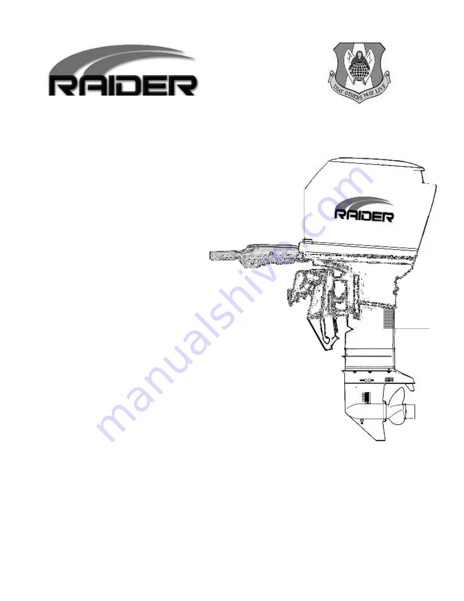
SERVICE MANUAL 


Two stroke Low pressure 


Direct Injection (TLDI) 


Multi-fuel  


Submersible 


This manual has been prepared for the United States Guardian Angels for 

service of the Multi-fuel, Submersible Outboard motor designed and manufactured 

under Contract No. N61331⑩11⑩C-0008, dated 3/4/11.  The data presented in this 

manual was revised as of August 2013 representing the latest revision. 


August 2013 

Summary of Contents for 50 HP TLDI

Page 1: ...has been prepared for the United States Guardian Angels for service of the Multi fuel Submersible Outboard motor designed and manufactured under Contract No N61331 11 C 0008 dated 3 4 11 The data pres...

Page 2: ...tors Parts can be found worldwide common with these three motors This manual This manual This manual This manual represents the production version of represents the production version of represents th...

Page 3: ......

Page 4: ...ter 5 Installing and Inspecting Electrical Components Chapter 6 Disassembling Inspecting and Reassembling Lower Unit Chapter 6 Disassembling Inspecting and Reassembling Lower Unit Chapter 6 Disassembl...

Page 5: ...G BATTERY SYSTEM 3 12 CHAPTER 4 DISASSEMBL CHAPTER 4 DISASSEMBL CHAPTER 4 DISASSEMBL CHAPTER 4 DISASSEMBLING INSPECTING AND ING INSPECTING AND ING INSPECTING AND ING INSPECTING AND REASSE REASSE REASS...

Page 6: ...DEWATERING VALVES THE OPERATOR MUST OPEN AFTER SUBMERSION 9 2 2 DE WATERING PROCEDURE 9 3 CHAPTER 10 TROUBLESH CHAPTER 10 TROUBLESH CHAPTER 10 TROUBLESH CHAPTER 10 TROUBLESHOOTING OOTING OOTING OOTING...

Page 7: ...r 1 Specifications Specifications Specifications Specifications 1 SPECIFICATIONS TABLE 1 1 2 OUTLINE DIMENSIONS 1 2 3 WHAT IS TLDI 1 4 4 FUEL SUPPLY SYSTEM 1 7 5 AIR SUPPLY SYSTEM 1 8 6 OIL SUPPLY SYS...

Page 8: ...cavenging system 5 port loop Charge Exhaust system Through hub Lubrication system Oil injection Cooling system Water cooling Water temperature control Thermostat with pressure relief valve Ignition Sy...

Page 9: ...1 2 2 O 2 O 2 O 2 Outline Dimensions utline Dimensions utline Dimensions utline Dimensions...

Page 10: ...n C Transom L 530 mm 20 9 in Transom UL 657 mm 25 9 in D 568 mm 22 4 in E 680 mm 26 8 in F 85 mm 3 3 in G 600 mm 23 6 in H 520 mm 20 5 in I 440 mm 17 3 in J 31 70mm 1 2 2 8 in K 490 mm 19 3 in Transom...

Page 11: ...system and Engine Control Unit ECU which performs precision control of fuel mixture injection timing and ignition timing to maximize combustion efficiency in the TLDI engine The result is better fuel...

Page 12: ...allows the Raider 50 horsepower outboard to function as a multi fuel engine Input Control Input Control Input Control Input Control Sensor Switch Control Control Control Control ECU Output Output Outp...

Page 13: ...or CPS Position Sensor CPS Position Sensor CPS Position Sensor CPS Crank position sensor is designed to sense the encoder located above the ring gear on the flywheel in order to detect crankshaft posi...

Page 14: ...injected into the combustion chambers The fuel regulator 8 regulates fuel pressure so as to keep it 70 kPa 10 psi higher than the pressurized air pressure 55OkPa Bopsi to inject fuel into combustion c...

Page 15: ...gh the air filter 1 and sends compressed air through to the air rail 3 The air regulator 4 regulates air at the optimum combustion pressure of 550 kPa 80 psi and the regulated air is injected into eng...

Page 16: ...2 air box 5 3 air box 6 and the air compressor 7 Ports 4 5 and 6 serve to lubricate the engine pistons while port 7 lubricates the air compressor TLDI includes an oil recirculation system in which the...

Page 17: ...1 10...

Page 18: ...Information 1 GENERAL PRECAUTIONS FOR SERVICING 2 2 2 2 1 1 1 1 2 SPECIFICATIONS AND STANDARDS USED IN SERVICING 2 2 2 2 3 3 3 3 3 LISTS OF POINTS FOR APPLYING SEALANT ADHESIVE AND LUBRICATION 2 2 2 2...

Page 19: ...2 2...

Page 20: ...2 1...

Page 21: ...in their original locations 8 As normal practice check disassembled parts for any wear or damage by first wiping them clean then washing them in solvent 9 With reassembly operations it is essential t...

Page 22: ...tion Measure with both ends supported on V blocks 0 05 mm 0 002 in Connecting rod Deflection Cylinder head Mating surface 0 03 mm 0 0012 in or less for scratches 0 03 mm 0 0012 in or less for distorti...

Page 23: ...the maximum and minimum points of wear in liner bore is 0 06 mm 0 0024 in or more Repair by polishing the surface plate starting with 240 to 400 grit sandpaper and finishing with 600 grit sandpaper Bo...

Page 24: ...oil resistance value L wire to G wire 0 5 to 0 9 mm 0 019 to 0 035 in 5311_ 15 20 C 68 F Thermostat Opening and closing of thermostat valve Valve start temperature 52 C 125 6 F Valve full open tempera...

Page 25: ...and upper and lower surface lip areas show wear cracks or damage When depth of wear is 0 1 mm 0 004 in or more Replace with new assembly Replace with new shaft Replace with new shaft 0 4 mm 0 016 in...

Page 26: ...lator Air pressure 550kPa 5 6 kg cm2 7 80 psi 7 Fuel regulator Fuel pressure Measured air pressure 70 kPa 0 7 kg cm2 10 10 psi 10 Air injector Measured value for resistance Operating condition check f...

Page 27: ...s When parts no longer conform to standard values Replace with new parts When parts no longer conform to standard values Replace with new parts When parts no longer conform to standard values Replace...

Page 28: ...ive Adhesive Adhesive Application points Application points Application points Application points 1342 1373B Adhesive 648 Primer 7471 518 1741 G17 Engine block Engine block Engine block Engine block P...

Page 29: ...Specified Specified Specified gear oil gear oil gear oil gear oil Power trim tilt Power trim tilt Power trim tilt Power trim tilt fluid 1 fluid 1 fluid 1 fluid 1 Remarks Remarks Remarks Remarks LT 2 L...

Page 30: ...Air hose L nipple 0 ring Fuel hose L nipple 0 ring Valve assembly O Air Air Air Air compressor compressor compressor compressor Air compressor piston Air compressor cylinder Air compressor piston pin...

Page 31: ...64 O O rings at 2 locations O O rings at 2 locations O O rings at 2 locations O O rings at 2 locations O Air rail 6 locations O Air rail 3 locations O O rings at 2 locations O O rings at 2 locations...

Page 32: ...ear case lubricating oil Gear case bolt Extension housing bolt Propeller shaft housing bolt O 2 Stern bracket section Stern bracket section Stern bracket section Stern bracket section Bracket bolt Bra...

Page 33: ...tsu Specified Specified Specified Specified gear oil gear oil gear oil gear oil Power trim Power trim Power trim Power trim tilt fluid 1 tilt fluid 1 tilt fluid 1 tilt fluid 1 Remarks LT 2 LOR 101 KS...

Page 34: ...rk plug 25 30 2 5 3 0 kg m Cylinder block and 0 3 0 4 Bolt M8 19 21 1 9 2 1 kg m 18 22 Bevel gear B Nut bevel gear B M12 40 58 4 6 kg m 14 15 Stem bracket Nylon nut 7 8 24 26 2 4 2 6 kg m Mount rubber...

Page 35: ...2 16 5 Special Tools 5 Special Tools 5 Special Tools 5 Special Tools...

Page 36: ...on pin tool 345 72215 0 For removing and tightening on the pulley nut For installing 0 rings on the fuel injectors For installing and removing the piston rings For installing and removing piston pins...

Page 37: ...ing pin tool A 345 72227 0 Spring pin tool B 345 72228 0 For removing and installing gear case needle bearing and propeller shaft housing For removing and Installing spring pins Clutch pin snap tool 3...

Page 38: ...onds Once the engine starts allow it to idle at 700 rpm for approximately for engine for approximately 15 seconds Once the engine starts allow it to idle at 700 rpm for approximately for 15 minutes 15...

Page 39: ...ing two 36 mm wrenches attach one to the crankshaft holder and use the other to loosen the pulley nut Installing Pulley Nut Installing Pulley Nut Installing Pulley Nut Installing Pulley Nut 1 Apply th...

Page 40: ...towards the crankshaft end in order to create a gap with the drive pulley 3 Insert plate A 3T5 72891 0 and plate B 3T5 72892 0 into the gap by mating the two knock studs 3T5 72897 0 on plate B with pl...

Page 41: ...place The beginning half is designed to insert easily the remaining half requires press fitting Piston Slider 3T5 Piston Slider 3T5 Piston Slider 3T5 Piston Slider 3T5 72871 72871 72871 72871 O O O O...

Page 42: ...e connecting FFP case assembly to high pressure fuel filter and the hose connecting high pressure fuel filter to air rail assembly 2 Air Hose Assembly 3T5 10088 0 Clamp 1 12 3T5 10087 0 Installed at t...

Page 43: ...2 24...

Page 44: ...MAINTENANCE TENANCE TENANCE TENANCE 3 3 3 3 1 1 1 1 1 PERIODIC INSPECTIONS 3 2 2 INSPECTING ENGINE OIL SYSTEM 3 3 3 INSPECTING FUEL SYSTEM 3 3 1 INSPECTING COMPRESSION SYSTEM 3 4 2 INSPECTING GEAR CA...

Page 45: ...rk gap 0 7 to 0 8 mm 0 0276 to 0 0315 in Pull Start O O O O Salt Corrison Starting system Rope Start O O O O Frey in rope Propeller O O O O O O O Wear bending chipping on blades slipping of cushion ru...

Page 46: ...nk prior to bleeding air from the piping Oil Filter and Oil Tank Oil Filter and Oil Tank Oil Filter and Oil Tank Oil Filter and Oil Tank Check the oil filter for water and foreign matter If present di...

Page 47: ...p switch 4 Remove all spark plugs 5 Remove all air injector and fuel injector connectors Accurate compression readings are only possible when all connectors are disconnected It should also be noted th...

Page 48: ...3 5...

Page 49: ...nd proceed carefully Remove the following components Split pin Replace with new pin Propeller nut Washer Propeller stopper or adapter Propeller or with drive sleeve Propeller thrust holder or washer R...

Page 50: ...3 7...

Page 51: ...er when operating the engine on land Be sure not to operate the engine in confined areas such as a boat house as the exhaust fumes contain toxic carbon monoxide gas Washing With Flushing Attachment Ho...

Page 52: ...locations Remove the gear case assembly from the drive shaft housing Bolt type H835 at 4 locations Inspect the following components Upper pump case Pump case liner Pump impeller Replace with new one K...

Page 53: ...3 10 Overview of Cooling System Overview of Cooling System Overview of Cooling System Overview of Cooling System Tubing Tubing Tubing Tubing...

Page 54: ...3 11...

Page 55: ...position clockwise 6 6 6 6 Inspecting Air Rail Pressure Inspecting Air Rail Pressure Inspecting Air Rail Pressure Inspecting Air Rail Pressure Refer to the description for Pressure Gauge Assembly list...

Page 56: ...nit Power Unit CHA CHA CHA CHAPTER 4 PTER 4 PTER 4 PTER 4 DISASSEMBLING INSP DISASSEMBLING INSP DISASSEMBLING INSP DISASSEMBLING INSPECTING AND REASSEMBL ECTING AND REASSEMBL ECTING AND REASSEMBL ECTI...

Page 57: ...4 2 1 1 1 1 Power Uni Power Uni Power Uni Power Unit t t t...

Page 58: ...tank with oil tank mounting bolts after then P P P P Type Type Type Type Disassemble the following components Wire harness connectors 3 Throttle cable from advancer arm Shift cable from shift arm Wate...

Page 59: ...oist to suspend the power unit while keeping it in the horizontal position Suspend slowly taking care not to catch the power unit on any of the wiring or hoses Remove crankcase head Remove with cautio...

Page 60: ...4 5...

Page 61: ...g it in the horizontal position with power unit suspended install the following components Crankcase head Apply a sufficient amount of heat resistant grease LOR 101 to the entire circumference of the...

Page 62: ...Sensor CrankPositioning Sensor CPS CPS CPS CPS Flywheel and Alternator Flywheel and Alternator Flywheel and Alternator Flywheel and Alternator Remove the following component CPS Remove the following c...

Page 63: ...ECU ECU abbreviation for the engine control unit Remove the following components ECU connector While pressing down on hook remove by prying gently with a flathead screwdriver Rubber mount bolt type H6...

Page 64: ...t connector Air injector connector Remove by pressing open the claws on either side with a flathead screwdriver and pulling out Bullet connectors for ignition coils When removing cable assembly with t...

Page 65: ...lator Removing Ignition Coil and Rectifier Regulator Removing Ignition Coil and Rectifier Regulator Removing Ignition Coil and Rectifier Regulator Remove the following components Ignition coil 1 Ignit...

Page 66: ...4 11...

Page 67: ...the air rail to release pressure from the air lines 2 Press on the core of the fuel valve located on the air rail to release pressure from the fuel lines Be sure to cover the fuel valve with a clean...

Page 68: ...4 13...

Page 69: ...olts at 3 locations Remove the following components Air compressor The air compressor is held in place by two knock pins these should be removed with a gentle tilting motion Drive belt Be sure to appl...

Page 70: ...4 15 Air Compressor Configuration Air Compressor Configuration Air Compressor Configuration Air Compressor Configuration...

Page 71: ...ter race when press fitting bearing Oil seal Wear and damage Replace with new one if defects are found 0 ring Scratches and wear Collar Wear and damage Crankshaft Wear and damage Cylinder Sliding surf...

Page 72: ...4 17...

Page 73: ...with the UP marking at the top Assemble the following components Nut torque 44 49N m 4 5 5 Okg m 32 36ft lb Washer 10 5 20 3 2 Pulley 0 rings apply LOR 101 Bushing Oil seal apply LOR 101 Bearings app...

Page 74: ...r head gasket Replace with new one Reed valve assembly Valve seat gasket Replace with new one Take care not to confuse the top and bottom or front and rear of the reed valve assembly Take care not to...

Page 75: ...4 20...

Page 76: ...pples Disassemble and pull out the stopper plate Air hose assembly Disconnect the hose joint on the compressor side Cooling water outlet hose Fuel return hose Air discharge hose Cooling water inlet ho...

Page 77: ...4 22 Air Rail Assembly Configuration Air Rail Assembly Configuration Air Rail Assembly Configuration Air Rail Assembly Configuration...

Page 78: ...gs Replace with new ones if problems are detected Clogged regulator strainer Clean if foreign matter is present Wear deterioration and damage on pressure hose Replace with new one if problems are dete...

Page 79: ...oper direction as shown in View A to the right Adapter Fuel injector Be sure to use the special tool when installing the 0 rings in the fuel injector Special tool 0 ring Setting Tool 3T5 72863 0 Refer...

Page 80: ...Hose Assembly Disassembling Fuel Hose Assembly Remove the following components Fuel hose assembly Lead wire band at 2 locations High pressure fuel filter Bolts at 2 locations Connections to FFP Connec...

Page 81: ...en the air vent screw Loosen the drain screw Hold a cloth in place to absorb spilling fuel when loosening Detach the following hoses Vapor discharge hose Vapor return hose Fuel inlet hose Hold a cloth...

Page 82: ...or Separator Configuration Inspecting Vapor Separator Inspecting Vapor Separator Inspecting Vapor Separator Inspecting Vapor Separator No Components Points to check 1 0 rings Wear deterioration and da...

Page 83: ...bly Assemble in the reverse order of disassembly Vapor separator assembly Bolt type H630 at 2 locations Washers at 4 locations Collars at 2 locations Rubber mounts at 2 locations Torque 4 6 to 6 3 N m...

Page 84: ...4 29 Fuel Feed Pump Fuel Feed Pump Fuel Feed Pump Fuel Feed Pump FFP FFP FFP FFP Configuration Configuration Configuration Configuration...

Page 85: ...ar deterioration and damage Replace if defects are detected 5 FFP Case Clogging by foreign matter and water 6 FFP assembly Dirt and foreign matter on lower intake port Cracks and damage on upper and l...

Page 86: ...4 31...

Page 87: ...14 to 16 N m 1 4 to 1 6 kg m 10 to 12 lb ft Adhesive to apply after degreasing thread area Three Bond 1342 Metal washers Always replace after disassembly Uppercase Assemble the following components Pi...

Page 88: ...ply Terminals Genuine engine oil Connect to the flat connector cable terminal by lining up with the mark and or on the FFP Assemble the following components FFP cable Attach cable to terminal by press...

Page 89: ...linder Installing FFP Assembly on Cylinder Installing FFP Assembly on Cylinder Install the following components FFP assembly Bolt type H630 at 2 locations Washer Rubber mounts Collars Torque 4 6 to 6...

Page 90: ...e following components Oil filter Oil pump bolt Oil pump Oil pipe 4 Remove by pulling the pipes 4 out from oil pump Remove the following components Oil level sensor cable Bolt type H630 Oil tank The o...

Page 91: ...Assembling Oil Pump and Oil Tank Assemble the following components Refer to chapter 1 Oil discharge pipe 1 air box Oil discharge pipe compressor Oil discharge pipe 2 air box Oil discharge pipe 3 air b...

Page 92: ...d it will be necessary to disconnect the rod snaps from the advancer arm Take care not to apply any force to the corresponding arm when disconnecting the ball joint Bolt type H635 including washers an...

Page 93: ...ing a pinching motion Take care not to apply force to the TPS lever Disassembling Disassembling Disassembling Disassembling TPS Disassemble the following components TPS assembly Screw type 420 pan hea...

Page 94: ...dy Disassembling Air Box and Throttle Body Disassembling Air Box and Throttle Body Disassemble the following components Bolt type H625 at 8 locations Clamp Air box cover Remove the following component...

Page 95: ...Assemble the Following Components Throttle body assembly Gasket Replace with new one Bolts H625 at 2 locations apply Three Bond 1342 Grease to apply Interacting surfaces of the throttle cam and rolle...

Page 96: ...ng Engine Block Disassembling Engine Block Disassembling Engine Block Disassembling Engine Block Cylinder and Crankcase Assembly Cylinder and Crankcase Assembly Cylinder and Crankcase Assembly Cylinde...

Page 97: ...4 42 Piston and Crankshaft Piston and Crankshaft Piston and Crankshaft Piston and Crankshaft...

Page 98: ...49 F 3 F Valve full lift height 3 mm 0 12 in or more Disassembling Cylinder Head and Head Cover Disassembling Cylinder Head and Head Cover Disassembling Cylinder Head and Head Cover Disassembling Cyli...

Page 99: ...ting Inspecting Inspecting Inspecting Use components and to measure distortion Straight gauge Thickness gauge Maximum limit 0 03 mm 0 001 in Cleaning Cleaning Cleaning Cleaning Clean using a scraper o...

Page 100: ...r Inspect the following components Outer exhaust cover Inner exhaust cover Cooling water nipple Inspecting Inspecting Inspecting Inspecting Check for scratches and distortion on mating surfaces Check...

Page 101: ...shaft holder and secure using the magneto nut Using two 36 mm wrenches use one to secure the crankshaft holder and the other to loosen the pulley nut After sufficiently loosening the pulley nut remove...

Page 102: ...ns Remove both and take care not to scratch the pinhole Remove the following component Piston pin Special tool Piston pin tool 345 72215 0 Position against piston pin then holding the opposite side by...

Page 103: ...Inspecting Piston Inspecting Piston Inspecting Piston Outer diameter of piston skirt using micrometer Standard value Service limit 67 96 mm 2 676 in Replace when 67 90 mm 2 673 in or more Measure at p...

Page 104: ...8mm 0 013 to 0 019 in Replace when 0 9 mm 0 035 in or more Pressing the ring on the piston crown place in ring gauge Use cylinder when ring gauge is not available Inspecting Crankshaft Inspecting Cran...

Page 105: ...component Piston pin clip Install only on one side first prior to installing piston pin Always use a new piston pin clip The piston pin clip gap should face in the opposite direction of groove Assemb...

Page 106: ...4 51...

Page 107: ...the crankcase Assemble the crankshaft and the cylinder using the Following procedures Points Points Points Points to to to to Note Note Note Note Make sure that all pistons are positioned perpendicul...

Page 108: ...he mating face Install the crank case bolts Tighten bolts in the proper order M8partialtorque 12to15N m 1 2to1 5kg m 8 9to11lb ft M8fulltorque 24to26N m 2 4to2 6kg m 17to19Lb ft Assembling Assembling...

Page 109: ...t covers then degrease Assemble the following components Exhaust cover gasket Replace with new one Inner exhaust cover Exhaust cover gasket Replace with new one Outer exhaust cover Fuel filter band Wa...

Page 110: ...omponents Installing and inspecting electrical components CHAPTER 5 CHAPTER 5 CHAPTER 5 CHAPTER 5 INSTALLING AND INSP INSTALLING AND INSP INSTALLING AND INSP INSTALLING AND INSPECTING ELECTRICAL CO EC...

Page 111: ...5 2 1 1 1 1 Wire Routing Wire Routing Wire Routing Wire Routing...

Page 112: ...5 3...

Page 113: ...5 4...

Page 114: ...5 5...

Page 115: ...5 6...

Page 116: ...5 7 Wiring Diagram 40B 50B EPTO...

Page 117: ...5 8...

Page 118: ...5 9...

Page 119: ...5 10...

Page 120: ...5 11...

Page 121: ...5 12...

Page 122: ...r lead wire 12 PTT solenoid switch A 35 Trimsender 13 PTT solenoid switch B 36 Trimmeter 14 Fuelinjector 37 15 Air injector 38 Water pressure meter 16 Ignition coil 39 Speedometer 17 Starter motor 40...

Page 123: ...Fuse holder assembly 28 Neutral switch 11 Starter solenoid 29 Warning horn Buzzer 12 PTT solenoid switch A 30 Main switch 13 PTT solenoid switch B 31 Lanyard stop switch 14 Fuel injector 32 PTT switc...

Page 124: ...cover 9 ECU 27 Cable assemblyC 10 Fuse holder assembly 28 Neutral switch 11 Starter solenoid 29 Warning horn Buzzer 12 30 Main switch 13 31 Lanyard stop switch 14 Fuel injector 32 15 Air injector 33...

Page 125: ...uelinjector YJB Yellow Black 20 21 WTS Watertemp sensor G Y Green Yellow 22 WTS Watertemp sensor TPS2andOillevelsensorGround B W Black White 23 24 25 1Airinjector Lg R Lightgreen Red 26 2Airinjector L...

Page 126: ...5 17 Note Slash shows stripe color of cable 2 2 2 2 Assembly Assembly Assembly Assembly...

Page 127: ...5 18 Wiring around solenoid Bracket...

Page 128: ...5 19...

Page 129: ...5 20...

Page 130: ...5 21...

Page 131: ...fuel injector and CPS crank position sensor Refer to the section Specifications and Standards Used in Servicing in Chapter 2 Rectifier Regulator Inspect For faulty connections or severed lines in the...

Page 132: ...f reading The contain approximate values for the1k range Note that values will vary depending on tester condition internal power supply testing range and the individual model Be sure to disconnect any...

Page 133: ...nsion replace spring Armature Measure the depth of the i nsul at or on the commutator When the distance at location does not fall within the 0 5 to 0 8 mm 0 02to0 03in range or when deformed from exce...

Page 134: ...5 25 5 Multi Fuel Electrical layout Connectors and wire pin outs Throttle Positioning Sensor Air Pressure Sensor RS 232 Pig Tail RS 232 Pig Tail...

Page 135: ...5 26 Fuel Injector 3 Fuel Injector 2 Fuel Injector 1 Water Temp Sensor Compressor Water Temp Sensor Natural safety switch...

Page 136: ...5 27 Kill Switch Crank Sensor Oil Level Sensor Grounds Air Injector 1...

Page 137: ...5 28 Air Injector 2 Air Injector 3 Coil 1 Coil 2 Coil 3...

Page 138: ...5 29 Fuel Pump Fuse Box Regulator Stator Complete Wiring harness...

Page 139: ...Inspection and Reassembly Lower Unit CHAPTER 6 CHAPTER 6 CHAPTER 6 CHAPTER 6 DISASSEMBLY INSPEC DISASSEMBLY INSPEC DISASSEMBLY INSPEC DISASSEMBLY INSPECTION AND REASSEMBLY TION AND REASSEMBLY TION AND...

Page 140: ...6 2 1 1 1 1 Configuration Configuration Configuration Configuration GEARCASE DRIVESHAFT...

Page 141: ...6 3 GEARCASE PROPELLERSHAFT...

Page 142: ...e disassembled from this outboard engine without having to remove the power unit Removing Propeller Removing Propeller Removing Propeller Removing Propeller Remove The Following Components Split pin P...

Page 143: ...Clutch Disassembling Propeller Shaftand Clutch Remove the various components using the following procedures Bolt type H 625 at 2 locations Propeller shaft housing with to Clutch pins napring Replace w...

Page 144: ...Bevel gear B 3 Drive shaft 4 Bevel gear A 5 Bevel gear A bearing 6 Bevel gear C Removal Procedure Removal Procedure Removal Procedure Removal Procedure 1 Insert onto spline 2 Attach to Special Tool Be...

Page 145: ...essary Propeller shaft Play between clutch and spline Replace as necessary Driveshaft Misalignment of driveshaft Wear on spline area Wear contact surface of needle roller bearing Replace Replace as ne...

Page 146: ...shimming gauge 3 Insert shimming gauge Note Taper T must be contacted to bearing outer surface firmly Opening slit of shimming gauge at N must be at the position12 o clock 4 Measure the gap between M...

Page 147: ...rrespondingadjustingshimsizes Gaugereading Backlash 0 31to0 62mm 0 0119to0 0244in Notes 1 Thevalueslistedinthetablerepresenttherangeofdial gaugereadingstakenusingthevariousspecialstools 2 Replaceshims...

Page 148: ...0to58N m 4to6kg m 29to43lb ft Special Tool BevelgearBnutwrench 346 72231 0 BevelgearBnutsocket 346 72232 0 ApplyingAdhesive ApplyingAdhesive ApplyingAdhesive ApplyingAdhesive Driveshaft BevelgearBnut...

Page 149: ...owingcomponents Clutchcam Clutchcamrod Camrodbushing Clutchcamspringpin 3 12 0 ring 2 4to5 8 0 ring 3 5to21 7 Special Tool SpringpintoolB 345 72228 0 Springpinsmustneverbereused Applygearoiltothe0 rin...

Page 150: ...Besuretoinsertshim betweentheoilseals o o Whiletakingcarenottoscratchthelipareaoftheoilseals insertthedri veshaftintothepumpcase o Carefullyfittheprotrudingsideofthepumpcaseliner intotherece ssionint...

Page 151: ...mbly Case Assembly Case Assembly Apply a thin coating of the specified rease to the spline area on the engine side of the drive shaft Grease Type LT 2 Install water pipe by first applying oil to the w...

Page 152: ...6 14...

Page 153: ...6 15...

Page 154: ...and Tilt Trim and Tilt Trim and Tilt CHAPTER 7 TRIM AND TILT TRIM AND TILT TRIM AND TILT TRIM AND TILT 7 7 7 7 1 1 1 1 1 MOTOR OPERATING INSTRUCTIONS 7 2 2 AFTER RAIDER IS STARTED 7 3 3 STOPPING RAID...

Page 155: ...to the shifter to minimize corrosion Conventional cable assemblies that connected the pull starter to the shifter over time corroded and became an issue This function is inside the Electronic Control...

Page 156: ...turn throttle control to SHIFT position or slower Move shift lever to FORWARD with a firm quick motion DO NOT shift engine with throttle control advanced beyond the shift DO NOT shift engine with thro...

Page 157: ...engine cover to raise engine to the full tilt position Tilt support will automatically engage While engine is tilted leave tilt run lever at TILT position If lever is at RUN position the tilt support...

Page 158: ...usly damaged by a collision at high or low speeds If you hit an object stop immediately and examine the engine for loose mounting hardware or clamp screws Inspect for damage to stern and swivel bracke...

Page 159: ...intake screens are not installed Make sure the water intake screens are not installed upside down upside down upside down upside down ramps must be forward If upside down the engine will overheat Obs...

Page 160: ...the starter can be removed d Lift starter assembly from Raider engine If starter cord is broken it might not be long enough to use as an emergency starter cord If intact cut cord from starter assembl...

Page 161: ...cedure The Raider has been designed for submersion Insure dewatering valves are closed Insure the oil tank is complete filled Dewatering is discussed in Chapter Dewatering is discussed in Chapter Dewa...

Page 162: ...Tiller Tiller Tiller Handle Handle Handle Handle Type Type Type Type CHAPTER 8 TILLERHANDLETY TILLERHANDLETY TILLERHANDLETY TILLERHANDLETYPE PE PE PE 8 8 8 8 1 1 1 1 1 TILLER HANDLE SHIFTER AND EMERGE...

Page 163: ...d Throttle DMCT allows a single operator to control a dual configuration outboard motors on the same RIB This system has a direct connection to both motors for positive throttle response and steering...

Page 164: ...you if seated in boat next to engine S S S Shifting hifting hifting hifting Always shift when the outboard is at idle speed Stop Stop Stop Stop slow engine to idle speed then shift lever to NEUTRAL po...

Page 165: ...T design features a one motor kick up feature in case only one of the motors hits a below water obstacle ease of connection even if the motors are not precisely placed on the I CAC the extended handle...

Page 166: ...g Dewatering Dewatering Dewatering CHAPTER 9 DEWATERING DEWATERING DEWATERING DEWATERING 9 9 9 9 1 1 1 1 1 LOCATION OF THREE DEWATERING VALVES THE OPERATOR MUST OPEN AFTER SUBMERSION 9 2 2 DE WATERING...

Page 167: ...submerged in fresh water to avoid exposure to the atmosphere should be resubmerged in fresh water to avoid exposure to the atmosphere should be resubmerged in fresh water to avoid exposure to the atmo...

Page 168: ...ider outboard is tilted into the RIB this allows the water to drain from the crankshaft The water will automatically run out when tilted into the RIB and turned sideways When a short pull to the pull...

Page 169: ...After engine has run at IDLE speed for 30 60 seconds turn drain valves to the RUN position IMPORTANT IMPORTANT IMPORTANT IMPORTANT DO NOT run the outboard with the drain valves in the DRAIN position m...

Page 170: ...it can be serviced to avoid prolonged exposure to the atmosphere keep it submerse in fresh water but get it prepared for your next mission as soon as possible Dewater the engine following the procedu...

Page 171: ...ting Troubleshooting Troubleshooting Troubleshooting CHAPTER 10 TROUBLESHOOTING TROUBLESHOOTING TROUBLESHOOTING TROUBLESHOOTING 10 10 10 10 6 6 6 6 1 TROUBLESHOOTING TABLE 10 7 2 TLDI SELF DIAGNOSING...

Page 172: ...from the outboard This Raider Outboard has silenced all alarms to avoid mission compromise The signals and warnings are recorded in the Electronics Control Unit that can be downloaded at the maintenan...

Page 173: ...n tank or bladder Replenish fuel and perform step 2 2 3 2 2 2 Air vent is closed Open air vent and perform step 2 2 3 2 2 3 Fuel not coming to fuellines 2 2 4 Fuel not fed to fuel lines after tank is...

Page 174: ...normal 600to640kPa 2 2 Fuel system High fuel pressure in airrail standard 600to 640kPa 87to93psi Low air pressure in airrail standard 530to570kPa 77to83ps i 2 3 Airsystem High air pressure in airrail...

Page 175: ...akage Replace 2 3 7 Damaged reed valve in air compressor 2 3 8 Worn cylinder or piston ring in air Compressor Inspect and replace as necessary 2 3 9 Faulty air regulator Replace 2 3 10 Path down strea...

Page 176: ...voltage 0 Flashing Self diagnosing function Indicates faulty components 0 0 Flashing Flashing Flashing 2 Engine turns over but does not start 4 Electricalsyst em Self diagnosing function indicates TP...

Page 177: ...or engine base gasket 3 1 5 Loose head bolts or crank case bolts Inspect and repair 3 2 1 Fuel is low or empty in tank Refer to step2 2 1 3 2 2 Air vent is clogged Refer to step2 2 2 3 2 3 Water in f...

Page 178: ...components 0 0 Flashing Flashing Rashing Self diagnosing functionindicatesfaultyTPSidling position 0 3 Enginestartsbutidli ng faltersorisunstable 3 4 Electricalsyst em Airinjector Variableidlingswitch...

Page 179: ...replaced Refertostep2 4 13 3 4 7 Malfunction Connect operationalinjectortoeachharnessandconfirmthatinject orgeneratesclickingsoundofnormaloperationwhenengi neisturnedover Cleanandreplaceasnecessary 4...

Page 180: ...airrail 6 2 Airsystem Highairpressureinairrail Fueltank FuelHose Fuelfilter 6 3 Fuelsystem Lowairpressureinairrail standard 550kPa 7 5 6kgf cm2 80psi Sparkplugs Airinjector 6 Noaccelerationatfull thro...

Page 181: ...infuelregulator Replace 6 3 10 Fuelleakage Inspectlinesandconnectorsforwearanddamage 6 3 11 lowairpressureinairrail Refertostep2 3 6 4 1 Refertostep2 4 5 6 4 2 Carbonbuildupinfuelinjector Inspect clea...

Page 182: ...ture too high temp indicator flashes 0 Continuous Flashing 0 Flashing 0 Flashing 0 Flashing 0 Flashing Battery voltage abnormally low battery indicator flashes 0 Flashing TPS not functioning 0 Flashin...

Page 183: ...rrectly installed or fault in remote control box Inspect repair and replace as necessary 10 1 1 Cooling water inlet clogged Inspect 10 1 2 Faulty water pump 10 1 3 Faulty thermostat 10 1 4 Cooling wat...

Page 184: ...hingFla shingFlashin gFlashingFla shingFlashin gFlashingFla shingFlashin gFlashingFla shingFlashin g High speedLow speedForcedidl ingLow speedLowspee dEnginestopFo rcedidlingLow speedForcedIdl ingLow...

Page 185: ...10 20...

Page 186: ...0211 1 Chapter 11 Servicing Servicing Servicing Servicing CHAPTER 11 SERVICING SERVICING SERVICING SERVICING 11 11 11 11 1 1 1 1 2 TESTRUNTANKANDTESTPROPELLER 11 2 2 INSPECTION 11 3 11 11 11 11...

Page 187: ...run tank The dimensions shown in the figure are the minimum that must be provided for a single engine whether it be in a tank partitioned for two engines Test Propeller Out to diameter 198 mm Out wid...

Page 188: ...roperly seat the sliding surfaces of the various parts in cases where pistons piston rings piston pins and cylinders have been replaced Perform the various breaking in steps listed in the table below...

Page 189: ...Requirements Fuel Oil Requirements Recommended Oil Recommended Oil Recommended Oil Recommended Oil Above 30 F Biodegradable Outboard Oil Below 30 F 100 Fully Synthetic 2 Cycle Engine Oil Recommended F...

Page 190: ...ce or prevent condensation from forming in the tank during storage 7 Remove propeller and check for damage A slightly bent propeller blade can hardly be noticed but will affect the performance of the...

Page 191: ...The anodes should be inspected at intervals and replaced when necessary or corrosion of the engine will increase If any anode has been reduced to 2 3 its original size 1 3 eroded it must be replaced...

Page 192: ...11 7 5 If the fuel hose has been disconnected reinstall it 6 Check fuel system for leaks Check fuel system for leaks Check fuel system for leaks Check fuel system for leaks...

Page 193: ...11 8...

Reviews: