PAGE 1 of 54
Ingenieurbüro CAT, M. Zipperer GmbH, Wettelbrunner Straße 6
79282 Ballrechten-Dottingen
Tel: + 49 (0) 7634 - 5056 - 800 Fax: + 49 (0) 7634 -5056 - 801
Internet:
www.jetcat.de
JetCat RX/RXi Turbines with V10 ECU
V1.2
Page 1: ...E 1 of 54 Ingenieurbüro CAT M Zipperer GmbH Wettelbrunner Straße 6 79282 Ballrechten Dottingen Tel 49 0 7634 5056 800 Fax 49 0 7634 5056 801 Internet www jetcat de JetCat RX RXi Turbines with V10 ECU V1 2 ...
Page 2: ...The Model Engine serial number has been deliberately removed defaced or altered 7 If a problem develops during the limited warranty period the Buyer shall take the following step by step procedure a The Buyer shall ship the Model Engine prepaid and insured to JetCat b The Buyer shall include a return address daytime phone number complete description of the problem and proof of purchase c The Buyer...
Page 3: ...ON THE GSU AND LED BOARD 19 JETCAT V10 ECU 20 SWITCHING ON THE ECU 20 SINGLE OR TWO CHANNEL OPERATION 21 HOW TO SET YOUR ECU FOR SINGLE CHANNEL OPERATION 21 SETUP FAILSAFE MODE 21 SETTING THE FAILSAFE 21 LEARN R C TEACH THE ECU TO THE R C SYSTEM 23 VERIFY FAILSAFE PROGRAMING 25 PREPARING FUEL AND FUEL SYSTEM 25 FUELING ON BOARD TANKS 25 PRIME THE PUMP AND SYSTEM NOT NEEDED FOR THE RXI 26 RUNNING T...
Page 4: ...N 34 MANUAL ADVANCED SECTION 35 JETCAT ECU FEATURES VERSION 10 00 35 Smoker valve 36 MENU STRUCTURE 40 MENU SELECTIONS 40 Selecting a Menu 40 Change Values Items 40 THE RUN MENU 40 THE MIN MAX MENU 41 THE R C CHECK MENU 41 THE INFO MENU 42 THE STATISTIC MENU 43 THE LIMITS MENU 43 AIRSPEED SENSOR 47 SPECIAL FUNCTION 53 Temperatur adjustment 53 Reset to Default Value 54 ...
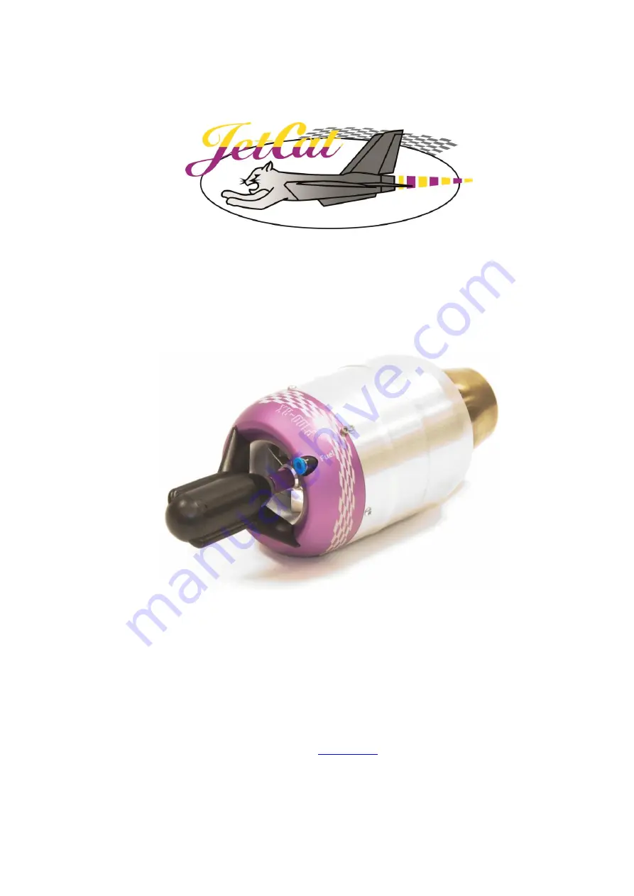
Page 5: ...centrifugal compressor compresses the incoming air which is mixed in the combustion chamber with fuel jet fuel kerosene and ignited The result is a rapidly expanding volume of gas that drives an axial turbine wheel The gas exiting the exhaust cone produces the required thrust for the jet model To start the turbine an electric motor is mounted on the front of the turbine During startup to preheat t...
Page 6: ...you might lose sight of model To avoid collisions with manned or unmanned aircraft land your plane immediately if a plane approaches Persons or animals must comply with the following minimum safety distances form a turbine model In front of the turbine 15 feet On the side of the turbine 25 feet Behind the turbine 15 feet Warning The construction and operation of the model and or turbine under the ...
Page 7: ... tracts or areas experiencing drought or dryness Obey all forest fire regulations and warnings by refraining from operating the JetCat turbine in restricted fire zones WARNING The overflight of people especially at low altitude is strictly prohibited Attention Always exercise caution around the hot parts of the turbine to avoid burns The outer case at the turbine stage and nozzle reaches 450 600 C...
Page 8: ...ing turbine support equipment Mounting turbine and fitting to tail pipe Fuel and electrical connections Battery power GSU and I O board ECU power setting failsafe and learn R C Preparing fuel and fuel system Starting and stopping the turbine Running states Troubleshooting Identify components 1 Turbine engine 1 Pump Cable only RX 1 GSU Ground Support Unit Terminal 1 Fuel Line 1 ECU Electronic Contr...
Page 9: ...le and the data bus jack accessible for plugging in the GSU 4 Ideally the pump should be mounted inverted using 4 40 screws and nuts through the flange holes tubes mounted down and electrical connections on top The pump requires a 1 diameter clearance hole The pump can also me mounted horizontally with cable ties or clamp Make sure that the fuel tubes will route so the fuel filter will be easy to ...
Page 10: ...otect the fuselage near the hot section of the turbine Do not mount electrical components fuel tubing or parts that could melt around the hot section of the turbine Inlet Protection Especially for models that have the air intake below the fuselage behind the nose wheel F16 for example there is the danger of small stones or dirt entering the turbine In these cases you must incorporate intake protec...
Page 11: ...PAGE 11 of 54 Connections Once you have unpacked and identified all the components follow the system diagram photo for all connections Complete System Connection Diagram RX ...
Page 12: ...UX channel OPTIONA L Not used for single channel operation Fuel input BVM UAT NOT INCLUD ED Fuel filter 6m m x 4m m ada pter Ballcoc k valve Not required Fuel pump ECU Batter y I O board Power data cable Receiver throttle input cable Connect to throttle channel 6mm tubing included with OPTIONA L UAT 4m m tubi ng ...
Page 13: ...the possibility of air being trapped inside and then coming out at an inopportune time It is also better not to affix it but to leave it free to slightly move ALWAYS use a gasoline compatible stopper in your fuel tanks Silicon stoppers swell and leak Hopper Tank UAT A hopper tank is recommended between the main fuel tank and the turbine JetCat highly recommends the BVM UAT for the hopper tank The ...
Page 14: ...e and ECU Connect the Flat cable to the LED I O board and ECU Connect a fully charged battery to the ECU To charge the battery refer to the Power section of this manual Throttle input Optional AUX input Power data cable I O board flat cable Battery Pump cable Fuel pump connection use either plug RX ECU Mini GSU I O board connections Plugs are interchangeable Pump Cabel RX ...
Page 15: ...PAGE 15 of 54 Complete System Connection Diagram RXi ...
Page 16: ...PAGE 16 of 54 System Connection RXi Photo To fueltank To receiver ...
Page 17: ...few weeks the battery should be disconnected Attention Fire A LiPo LiFePo battery can explode if incorrect charge parameters are used You should therefore always refer to the manufacturer s charger instructions NEVER charge the batteries unattended Do not exceed the batteries maximum allowed charging current READ AND OBEY WARNINGS ON BATTERY BEFORE CHARGING Always ensure the batteries are at their...
Page 18: ...me The real time nature of the ECU allows the operator to adjust the turbine s parameters even when the turbine is running GSU Control Panel Descriptions OPTIONAL Mini GSU Part 61161 00 With all the functionality of the larger version and because of its small size and weight it can be mounted in the model providing direct access to all information and functions ...
Page 19: ... for the data bus and a display for the current status of the ECU The LED I O board also features a pushbutton switch function to learn your R C system calibrate EGT probe or reset all parameters back to default when powered up These procedures are described later Description of LEDs on the GSU and LED board Please take the time to understand the table above especially the descriptions for the Sel...
Page 20: ...no servo pulse then there is a 60 second delay if the ECU is immediately powered off To force the ECU to power off simultaneously press the Manual and Run switches on the GSU The ECU can also be turned on without the receiver being powered on To do this there is a switch on the ECU labeled on and with a ballpoint pen or similar device press the switch for 5 seconds Settings can now be made or the ...
Page 21: ...N Turb Ctrl OFF Aux channel enabled for speed limiter functions and or Smoker Turbine control disabled You still need to use the AUX channel for speed limiter and or smoker functions but the turbine control will be in Single Channel Mode Not Used Single Channel Mode Totally disable the AUX channel input for turbine control speed sensor and smoker functions AUX channel wire does not need to be conn...
Page 22: ...rum radios there are two different ways to set the failsafe It is either accomplished by the transmitter s failsafe menu or by binding the receiver to the transmitter Refer to your transmitter s manual on how to set the failsafe To set the failsafe you must execute the following steps It is VITAL that these steps be performed in this order for the failsafe feature to operate properly YOU MUST PERF...
Page 23: ...d to advance through the learn R C sequence described below This feature is useful when the GSU is not available Keep in mind that the LED s on the I O board are the same as the GSU for Standby Pump running and OK Release Select Menu only after the three LED s display the following blink sequence LED Blink Sequence Standby Man Yellow Pump running Red OK Green The GSU screen will display 3 This pro...
Page 24: ...n OK LED will illuminate again and initiates the learn mode for the three position auxiliary channel 8 Move the auxiliary channel to the minimum position for Off and press Select Menu or the LED I O board button switch again to store the R C system s pulse width for immediate shutdown of the turbine The green OK LED will turn off and the red Pump running LED will illuminate The GSU screen will dis...
Page 25: ...o operate the turbine in a safe manner Preparing fuel and fuel system Warning Obey local laws for the transportation and storage of fuels Fire warning When mixing the fuel with oil or when operating fueling defueling etc never handle near an open flame Please do not spill or empty fuel to the ground The JetCat engine can use deodorized kerosene 1 K kerosene or Jet A1 for fuel Fuel must be mixed wi...
Page 26: ... runs at press either the or while pressing the Change Value Item key It is best to lower the pump voltage back down to the 0 5V default amount when finished Running the turbine for the first time The Checklist Before Running the Turbine Charge ECU Battery You must read and obey warnings on the LiPo LiFePo battery pack Prepare CO2 fire extinguisher Check fuel lines and filter Make sure they are cl...
Page 27: ...ly stopped rotating 4 As soon as the turbine stabilizes at idle speed the green OK LED will illuminate indicating that thrust control is now handed over to the pilot The throttle stick must be in the idle position for the green OK LED to illuminate After the start process is initiated the following occurs 1 After the start signal has been received the starter motor is shortly activated to give an ...
Page 28: ... e g a model fire the automatic cooling process may contribute additional oxygen To immediately discontinue the cooling process bring the throttle stick to idle throttle trim to the minimum position and the AUX switch to Off Exhaust temperature in C Battery voltage Turbine RPM In 1000 units Battery icon shown full Off Condition none indicated Igniting plug defective Failsafe active transmitter off...
Page 29: ...PAGE 29 of 54 Flashing E EGT sensor defective Last Off Condition Low RPM shut off from previous run ...
Page 30: ...is always displayed on the GSU screen in the STATE selection in the RUN menu When the turbine is starting the GSU will also display the current state on the bottom line of the display Whenever the engine is in cooling mode or the starter is tested with the Ignition key the top line of the GSU display will flash Cooling Exhaust temperature in C Current pump voltage Started directly from GSU explain...
Page 31: ...tes Stabil Turbine successfully accelerates to the idle RPM then automatically increases speed to about 30 higher RPM When this speed is maintained consistently for at least one second the turbine will proceed to the next state Learn LO Learn LO In this state the turbine automatically decreases RPM to the idle speed As soon as idle speed is attained with the throttle stick in the idle position the...
Page 32: ...minimum value A dislodged EGT sensor can trigger this shut down 11 HiTempOff EGT exceeded the maximum range 950 C 12 GlowPlug Defective kero glow plug 13 WatchDog ECU processor was locked out usually from static discharge or voltage spike in power supply 14 FailSafe Turbine was shut down from a failsafe timeout condition 15 ManualOff Turbine was shut off by using the GSU 16 PowerFail The power fai...
Page 33: ... full commands from the throttle stick Programming alteration in R C transmitter Check alignment with RC Check menu Re align ECU to the R C system Turbine ignites but the start process is discontinued Air in fuel feed lines Fuel pump not running Air leaks in fuel system Examine all Festo fittings nipples clunk filter etc Check for fuel filter clogs Test the pump in Test Functions menu as soon as t...
Page 34: ...ious run Sample of displayed values Tim Time 4 0 R RPM 0 S Set RPM 0 EGT Temp 0 Pmp Pump V 0 0 Sta State 0 Th Thr pulse 0 Au Aux pulse 0 Bat Batt volts 0 AirS Air Speed 0 SetS Set Air speed 0 See the Explanation for Turbine Shut Down for a description of each state code How to diagnose a shut down from the saved data Symptom Engine shut off state Possible Reason Engine quits with a trail of white ...
Page 35: ...e GSU terminal without the R C transmitter Support for parallel connected turbines multi engine models With an optional smoke system the ECU can be programmed to generate warnings for low battery voltage low fuel or Fail Safe Built in data logger functions The data for the last 17 minutes of operation will be stored at a resolution of one sample per second and can be read by the optional PC softwa...
Page 36: ...osition and the turbine is running To be able to use this function it is necessary that the AUX channel is activated this is the parameter AUX channel func see below must not be adjusted to NOT USED Smoke Each JetCat Bus pump can be switched between fuel and smoke pump factory setting is fuel pump To change the setting switch off receiver connect only the pump you want to adjust RXi disconnect the...
Page 37: ...PAGE 37 of 54 The smoke flow can be set up by the Limits Menu Smoke Flow Press the Change Value key and change the value by pressing the and key ...
Page 38: ...PAGE 38 of 54 Connection Diagram of the Smoke System ...
Page 39: ...ype Engine B2 P20 SE SX C4 P140RX P180RX P200RX D8 E16 P300RX P400RX Smokerpumpe PRO The Smokerpumpe PRO can t be switched because it s no Bus Pump further it is impossible to set up the flow by GSU Proceed according the Smokepump PRO manual ...
Page 40: ... front of the value if it can be changed The RUN Menu As soon as the ECU is switched on the Run menu is displayed In the lower display line the actual turbine RPM is indicated In the upper display line the following selections can be monitored Use the buttons alone for selecting the different parameters Value Explanation Temp Current EGT Exhaust Gas Temperature The units C or F can be selected in ...
Page 41: ...x values can be reset by pressing Change Value key The values are only valid during and after the actual run By switching on the ECU they are reset The R C Check Menu All parameters in this menu are for informational purposes only and will vary in accordance with R C input Value Explanation Throttle StickPulse Position of the throttle stick by percentage 0 100 Position units of the throttle stick ...
Page 42: ...Q L OffFuelQ Minimum fuel quality during the last turbine run Fuel quality by shut off at the last turbine run L BubblCnt L Bubble Tim Number of bubbles counted during the last turbine run Timefram in seconds of the bubble count during the last turbine run Last Run Time Last turbine run time Last Fuel Count Quantity of fuel consumed during the last turbine run Last Off PmpVolt Volts applied to the...
Page 43: ...nimum RPM Turbine idle speed If IdleRPM SET or Idle Ramp Set is enabled by Barom Auto Tune it will further appear Auto in the display and the RPM is set by ECU Maximum RPM F Turbine maximum speed Indicate the thrust at full throttle By varying the RPM this value call the related thrust of the turbine This provides a save and easy way to limit the maximum thrust Lowidle RPM Reduced idle speed This ...
Page 44: ...n t be disabled Fail Safe delay Delay in seconds before Fail Safe function will be activated While this time the turbine speed run on the last valid stick pulse HOLD adjustable range 0 1 20 0 seconds After expiration of this term the Fail Safe Time Out starts see next point Fail Safe Time Out Delay in front of Fail Save cut off While this time the turbine speed is set to the Fail Save RPM next poi...
Page 45: ...e valve will be pulsed if the turbine has reached its maximum RPM Disabled No function off Note The smoke warn function is switched off while the throttle stick is in idle position IdleThrResponse Adjustment of the throttle response acceleration by idle up to average speed Fast default setting Normal average acceleration Slow slow acceleration for excessive warm weather or for operate more than 10...
Page 46: ...nual SpeedRegVal I See chapter Air Speed Control of the manual SpeedRegVal D See chapter Air Speed Control of the manual MinRPM SpdCtrl See chapter Air Speed Control of the manual TEST Menu Before activating the purge pump mode ALWAYS remove the fuel feed line connected to the turbine Pump Test Purge Fuel allows the fuel pump to operate without the turbine running However if the fuel feed line is ...
Page 47: ...ck directly alters turbine thrust When the Airspeed Sensor is plugged into the ECU it automatically establishes speed control mode In speed control mode the turbine thrust is automatically controlled to keep the model at a predetermined speed and or to limit the model s maximum speed Speed control mode features several functions measurement and storage of maximum and average flight speeds measurem...
Page 48: ...meters of speed regulation can be predetermined Limits menu parameters assigned to the Airspeed Sensor Parameter Explanation MAX LIMITAIRSPD Maximum allowed flight speed of the model in km h If this speed is achieved turbine thrust is automatically reduced to keep the model from exceeding the maximum limit This safety option is always active despite the position of the AUX switch Max AirSpeed Maxi...
Page 49: ...assigned as follows Standard assignments of the AUX switch Position SW0 Off turns the turbine off immediately Position SW1 Start Standby normal thrust control Position SW2 AutoOff normal shutdown method With the Airspeed Sensor connected to the ECU the AUX switch positions SW0 and SW2 include the expanded functions that are covered in the above parameters table These expanded assignments are only ...
Page 50: ...osition the current flight speed is assigned and recorded as the Max AirSpeed parameter WARNING When the AUX switch is set in the SW0 position the model must be flying faster than 40 km h otherwise the turbine will shut off LIN Speed Ctrl Cruise Control mode with linear speed regulation to the throttle stick position Flight speed is controlled between the values of the Min AirSpeed throttle stick ...
Page 51: ...he minimum throttle stick position corresponds to the parameter Min AirSpeed and the maximum throttle stick position corresponds to the parameter Max AirSpeed b If flight speed 40 km h when this function is activated the turbine will shut off normal AutoOff function Airspeed Sensor Mounting Experiments indicate that the Airspeed Sensor is more accurate when the pitot tube is side mounted on the wi...
Page 52: ...water column to the altitude of the differential pressure sensor or Pitot tube if used Press the key INFO on the GSU to define the zero point 5 Raise the end of water column to a level of 40cm above the defined zero point now press the MIN MAX key to store this value You should read in the right upper edge of display h 40 0 You can check the calibration by moving the water column up and down The v...
Page 53: ...ess the little key on the LED board The LED s indicate the following blink sequence LED Blink Sequenz Standby yellow Pump running red OK green The dispaly of GSU indicate simultanously Release Key to Learn RC While this sequence hold the key SelectMenu don t realease it Release the key if the three LED s indicate this blink sequence LED Blink Sequenz Standby yellow Pump running red OK green The Di...
Page 54: ...U indicate simultanously Release Key to Learn RC While this sequence hold the key SelectMenu don t realease it After awhile of ca 15 seconds the LED s indicat the folowing blink sequence LED Blink Sequenz Standby yellow Pump running red OK green While this sequence hold the key SelectMenu don t realease it Releas the key not before the LED s indicate following sequnce LED Blink Sequenz Standby gel...