


EPC-7 Hardware Reference
7
7
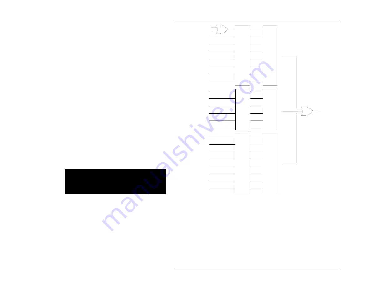
IRQ1
IRQ2
IRQ3
IRQ4
IRQ5
IRQ6
IRQ7
RRDY
WRDY
SYSFAIL
BERR
ACFAIL
WDT
SIGNAL FIFO
VXRCP
PC
architecture
IRQ10
VXIbus
interrupts
VME
interrupt
state
register
VME
interrupt
enable
register
VME
event
state
register
VME
event
enable
register
TTLTRG0
TTLTRG1
TTLTRG2
TTLTRG3
TTLTRG4
TTLTRG5
TTLTRG6
TTLTRG7
VXIbus
TTL
triggers
Trigger
latch
register
Trigger
interrupt
enable
register
Interrupt-causing signals are visible in three state registers. Most of these are
unlatched, meaning that a read of the state register shows the actual state of the
signals at the instant of the read.
The exceptions are (1) BERR, which is a "sticky" bit, meaning that the bit signifies
whether BERR had ever been asserted (the VXR register bit), and (2) the TTL trigger
signals, which for interrupt purposes are taken from the trigger latch register. The
convention used is that a 0 bit signifies an asserted (interrupting) state.
The primary purpose of the state registers is to let the interrupt handler software
determine which interrupts and events generated the IRQ10 interrupt to the processor.
Page 72
Artisan Technology Group - Quality Instrumentation ... Guaranteed | (888) 88-SOURCE | www.artisantg.com