


EPC-7 Hardware Reference
1 2
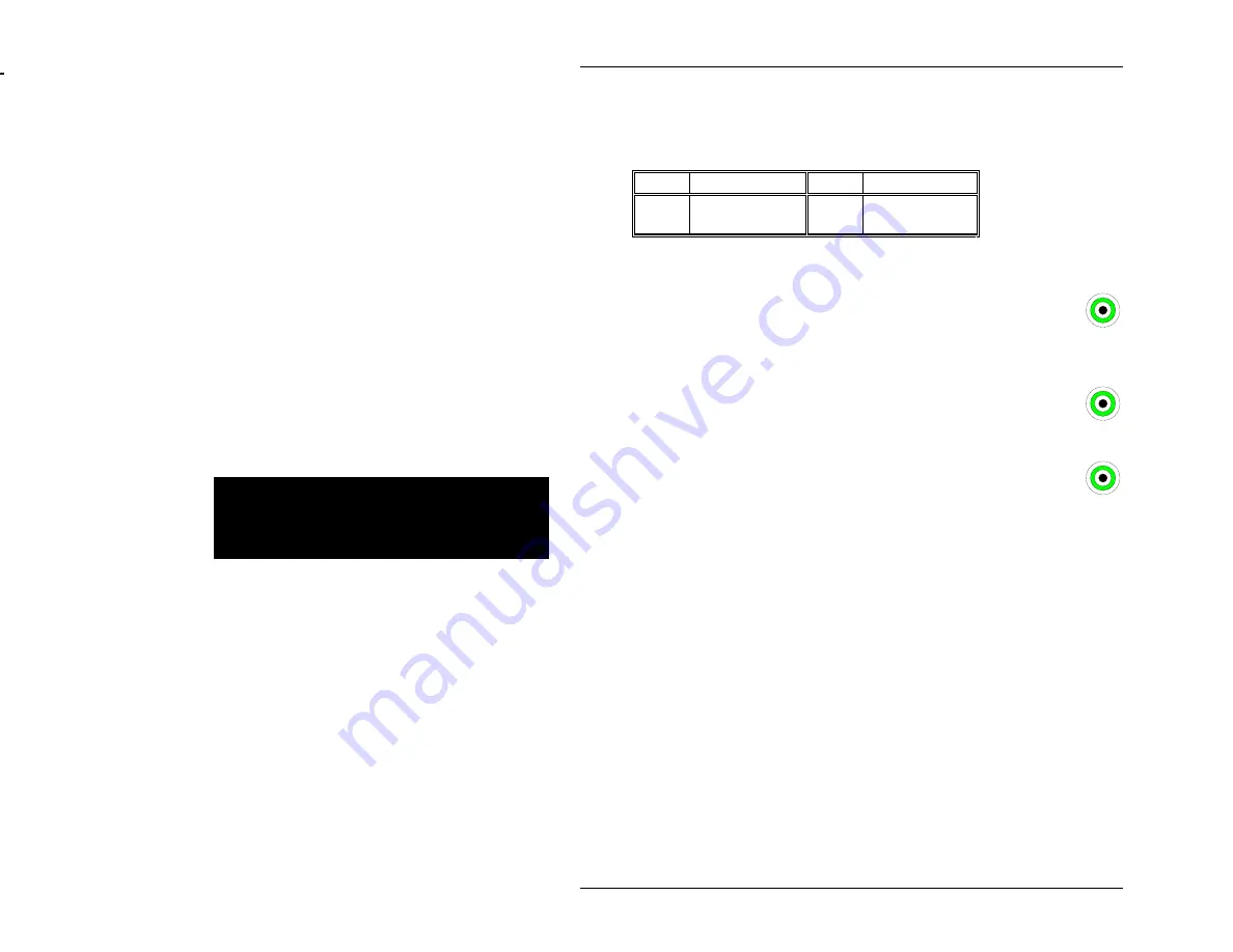
The speaker header on the EPC-7 circuit board is defined in the
table below.
6
Pin
Signal
Pin
Signal
1
Reference
voltage
2
Speaker
tone
Table 11. Speaker Header Pin-out.
The front-panel CLK-IN connector is a miniature SMB coax
connector. The input signal must be a TTL signal capable of driving a
74F04 input (interface circuit must source a Vol=0.5V max @ 1mA
sink and must source a Voh=2.4V min @ 500uA source current
The front-panel CLK-OUT connector is a miniature SMB coax
connector. It is a TTL output signal. CLK-OUT can drive a 50 ohm
line to 2.25V.
6
The front-panel TRIG connector is a miniature SMB coax connector.
Whether it is an input or output is determined by the external trigger
register (refer to Chapter 7,
VXIbus Interface
). The input
signal must be a TTL signal capable of driving a 74F04 input (see
CLK-IN). As an output, TRIG can drive a 50 ohm line to 2.25V.
VXI Signal Usage
The following table shows the usage of the VXI expansion interface signals on the
"main" P1 connector (the leftmost of the two P1 connectors). The "use" column
defines how the signal is used. I denotes input, O denotes output, IO denotes
input/output, P denotes power, G denotes ground, and blank denotes unused and
unconnected. Superscripted numbers represent notes.
Page 38
Artisan Technology Group - Quality Instrumentation ... Guaranteed | (888) 88-SOURCE | www.artisantg.com