


VXIbus Interface
7
7
VME Modifier Register
VME
WA23-22
BORD
IACK
AM5
AM4
AM2
AM1
8151
This register is also used when the EPC-7 makes an access through its E page to the
VXIbus. Bits 7 and 6 provide VXI address bits A23 and A22, respectively. Bits 3-0
define the value placed on the associated VXI address-modifier lines. Register bits
are not defined for the address-modifier AM3 and AM0 lines since, for all defined
address-modifier values in the VMEbus specification, AM3 is 1 and AM0 is the in-
verse of AM1. Therefore these two bit values are generated by hardware.
BORD Byte order. This bit controls the ordering of data bytes for D16 and D32
VXIbus accesses. If 0, the bytes are transmitted in little endian (Intel) order;
if 1, byte-swapping hardware transmits the bytes in big endian (Motorola)
order.
IACK This bit, when set, is used to define the VXIbus access as an interrupt ac-
knowledge cycle. The interrupt being acknowledged must be encoded by
software as a value on address lines A1-A3.
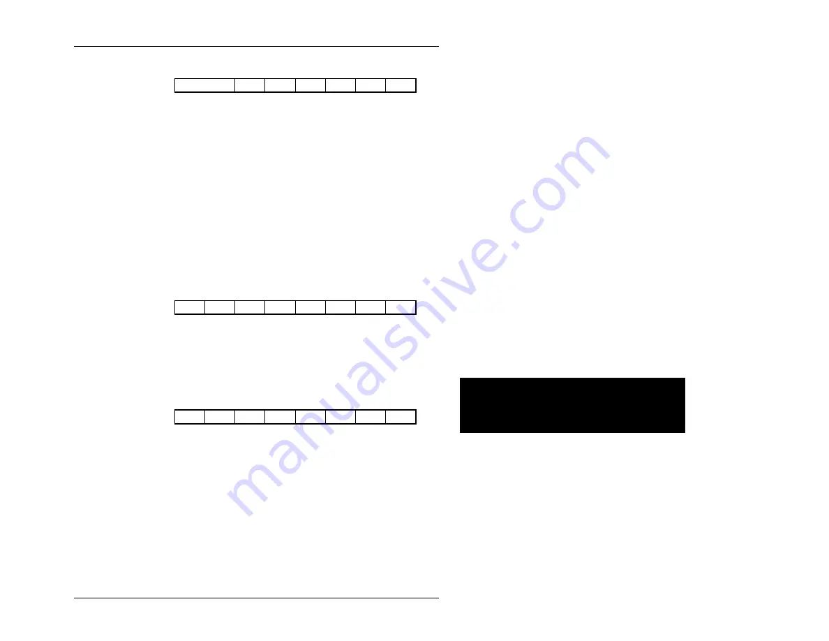
VME Interrupt State Reg
IRQ7
IRQ6
IRQ5
IRQ4
IRQ3
IRQ2
IRQ1
MSGR
8152
This read-only register defines the state of the VXI and message interrupts.
IRQx
If clear (0), the associated VXI interrupt line is asserted.
MSGR If clear (0), a message interrupt is being signaled. MSGR is clear if both of
bits RRDY and WRDY in the response register are clear.
VME
Interrupt
Enable
Reg
IRQ7
IRQ6
IRQ5
IRQ4
IRQ3
IRQ2
IRQ1
MSGR
8153
This is a mask of the interrupt conditions in the interrupt state register. A 1 denotes
that the corresponding interrupt is enabled. If any bit in this register is a 1 and the
corresponding bit in the interrupt state register is a 0, the EPC-7 IRQ10 interrupt is
asserted. Software may then examine the interrupt and event state registers to deter-
mine the cause.
Page 59
Artisan Technology Group - Quality Instrumentation ... Guaranteed | (888) 88-SOURCE | www.artisantg.com