


Configuring the BIOS Setup
The BIOS displays the configuration information in hexadecimal format.
RadiSys EPC-7 EXM Setup, System BIOS V3.05
50MHz 486, 16 MBytes memory
ID
OB1
OB2
Slot
0
FF
00
00
1
FF
00
00
F10 = Okay
2
FF
00
00
ESC = Cancel
3
FF
00
00
4
FF
00
00
5
FF
00
00
Figure 8. EXM Setup Menu.
EXMs must be defined in this screen so the BIOS can correctly identify and initialize
each one at boot-up. Each EXM must be listed by slot number, ID and two option
bytes as defined below.
4
4
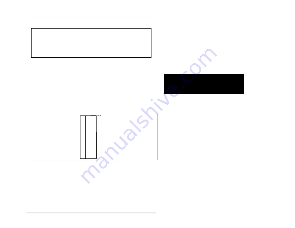
SLOT
indicates the EXM slot in which the EXM is installed. See
the figure below to determine which slot each EXM occupies. Note
that, when installed, the floppy disk drive occupies EXM
slot 0. Dotted lines indicate EXM slot numbers for an optional
EPC-7MC module carrier.
C
P
U
0
1
2
4
3
5
Figure 9. EXM Slot Numbering.
ID
is a hard-wired ID value. Each type of EXM has a unique ID value.
OB1/OB2 are two "option" bytes of configuration information.
All slots
not
occupied by an EXM module should show an ID of FF and OB1/OB2 of
00 00 indicating that no EXM is present. This includes slot 0 if the floppy drive is
installed.
Page 19
Artisan Technology Group - Quality Instrumentation ... Guaranteed | (888) 88-SOURCE | www.artisantg.com