


6. Connectors
This chapter specifies the details of the connectors of the EPC-7.
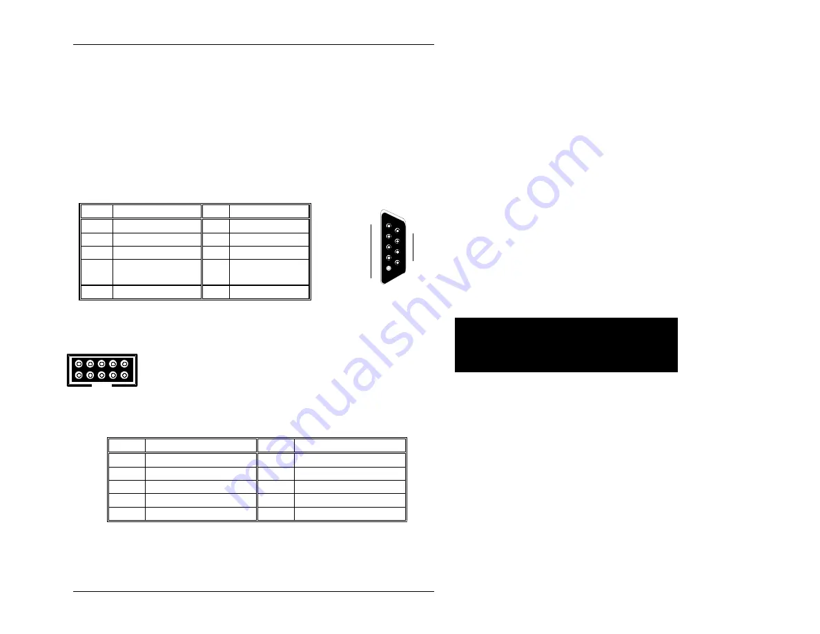
The DB-9 COM1 serial port connector is defined in the
following table.
6
6
Pin
Signal
Pin
Signal
1
Carrier detect
6
Data set ready
2
Receive data
7
Request to send
3
Transmit data
8
Clear to send
4
Data
terminal
ready
9
Ring
indicator
5
Signal
ground
1
5
6
9
Table 6. DB-9 Pin-out.
1 3 5 7 9
2 4 6 8 10
A second serial port, addressable as PC serial port COM2,
exists in the form of a 10-pin header on the printed-circuit
board near the bottom of the front panel. Pin 1 is the pin
closest to the front panel and the bottom of the EPC-7
printed circuit board. The header is defined in the table
below.
Pin
Signal
Pin
Signal
1
Carrier detect
6
Clear to send
2
Data set ready
7
Data terminal ready
3
Receive
data
8
Ring
indicator
4
Request to send
9
Signal ground
5
Transmit
data
10
Unconnected
Table 7. COM2 10-Pin Header Pin-out.
Page 35
Artisan Technology Group - Quality Instrumentation ... Guaranteed | (888) 88-SOURCE | www.artisantg.com