


VXIbus Interface
3. The unused address lines A31-A16 may float when not being used. Registers
8150 and 8130 must be set so that each line is a 1.
Set register 8130 to FCh and register 8150 to FFh.
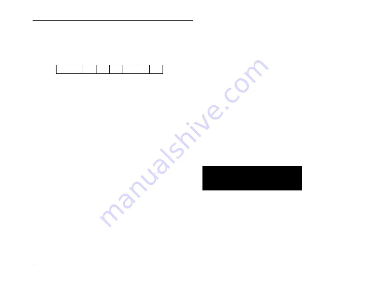
4. Set the access mode in the VME Modifier Register (8151) as follows:
7
7
VME
WA23-22
BORD
IACK
AM5
AM4
AM2
AM1
(Note that register bits are not defined for the VMEbus address modifier lines AM3
and AM0 since, for all defined address modifier values in the VMEbus specification,
AM3 is 1 and AM0 is the inverse of AM1. Therefore these two bit values are
generated by hardware.)
Bits 7 & 6 Since the A16 space does not use VMEbus address lines A23 &
A22, set these values to 1.
VME WA 23-22 = 11
Bit 5
Set the byte order to "little endian".
BORD
=
0
Bit 4
Clear the IACK bit so this is not an interrupt acknowledge cycle.
IACK
= 0
Bits 3-0
Use the address modifier (in binary form) to determine the
appropriate values for these bits. 2Dh = 00
10
1
10
1b
Bit 3 (Address Modifier bit 5) = 1
Bit 2 (Address Modifier bit 4) = 0
Bit 1 (Address Modifier bit 2) = 1
Bit 0 (Address Modifier bit 1) = 0
Thus, 8151 should be set to 1100 1010 or CAh.
5. Map the address.
Add the A16 address to the "E page" address
Addr
←
E0 A16 address
Page 69
Artisan Technology Group - Quality Instrumentation ... Guaranteed | (888) 88-SOURCE | www.artisantg.com