7
© 2017 Proceq SA
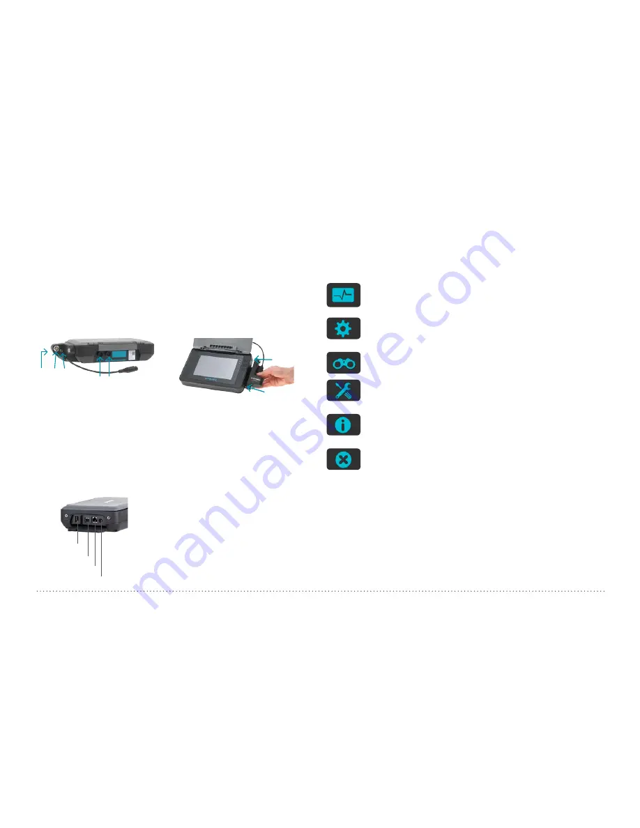
Probes connection Profometer 6
Connect the universal probe to either of the two sockets
or
on the
upper side of the Profometer touchscreen using the probe cable.
Profometer Corrosion
Mount the interface box on the right side of the Profometer touchscreen
using the attached screws
and
and connect the cable to either of
the two sockets
or
on the upper side of the Profometer touchscreen.
Connect the electrode signal cable to socket
and the ground cable to
the socket
of the interface box. Wheel electrodes: connect the path
measurement cable to socket
of the interface box.
USB Host:
Connect a mouse, keyboard or USB stick.
USB Device:
Connect application specific probes and PC.
Ethernet:
Connection for firmware upgrades.
Power Supply:
Connect the power supply through this connection.
USB Host
USB Device
Ethernet
Power Supply
2.2 Main Menu
On start up, the main menu is displayed. All functions are accessible
directly via the touchscreen.
Return to the previous menu by pressing the back button or the return
icon (arrow) at the top left of the touchscreen.
Measurement
Select to access either Cover Meter or Corrosion measuring
modes.
Settings
Application specific settings.
Explorer
File manager application for reviewing saved measurements.
System
Select your preferred interface language, date and time set-
tings and power saving options.
Information
Open documentation (Operating Instructions and additional
PDF files) and device info.
Power off
Switch off the device.
2.3 Upgrade procedure
The following procedure has to be performed in order to upgrade to Pro-
fometer 630 AI / 650 AI functionalities from a Profometer 600 unit or to
unlock Profometer 600 / 630 AI / 650 AI Cover Meter functionalities on a
Profometer Corrosion unit.
The Activation Key can be provided together with the initial purchase
(when a Profometer 630 AI or 650 AI unit is supplied) or can be ordered
anytime after the initial purchase in order to upgrade / unlock to further
functionalities.


