© 2017 Proceq SA
14
Locating Mode
Profometer
600
Profometer
630 AI
Profometer
650 AI
1
2
3
4
5
6
7
12
11
10
9
8
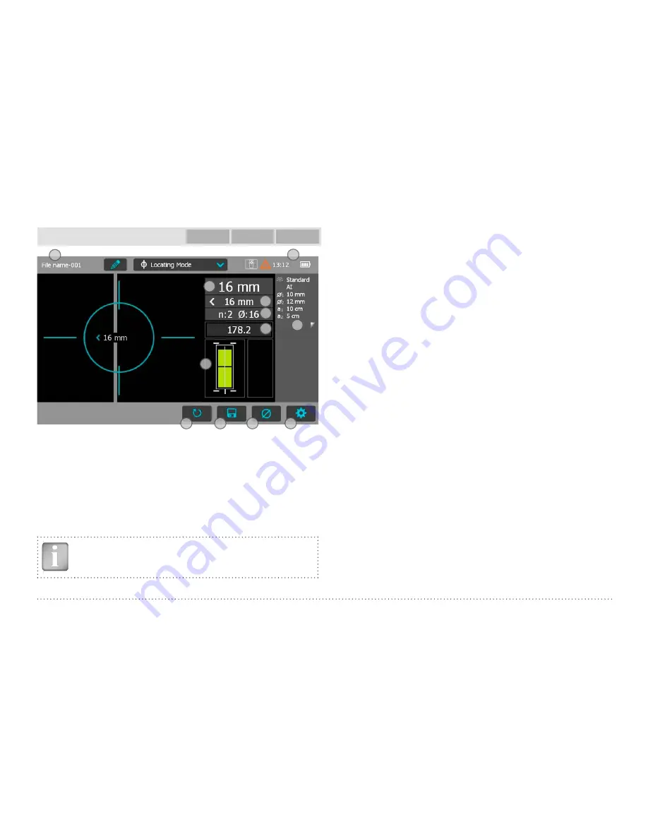
Figure 7:
Locating Mode
1
File name:
enter the file name and tap return. Saved measurements
will be stored with this file name. If several measurements are made
under the same filename, a suffix increments after each measure-
ment and follows the file name.
2
Probe connected, current time, battery status and warning triangle
for zeroing the probe when needed: after 5 minutes in orange, after
10 minutes in red.
NOTE! Tap on the triangle to perform zeroing.
3
Display
of selected Settings:
• Measuring Range
• Type of correction (None, AI, NRC, CAL)
• 1
st
and 2
nd
layer rebar size and spacing
• Cover Offset (if set)
• Probe Direction X: Undefined direction
^, v, <, >: On vertical wall, probe head towards
up, down, left, right
_, ˉ: On horizontal surface, on soffit
4
Settings:
switches to the settings menu
5
Rebar Diameter:
measuring of rebar diameter
6
Store measured data
7
Restart: all data of current measurement are deleted
8
Actual Cover
9
Distance to the nearest rebar
10 Nos. / Measured diameter
11 Signal strength
12 Coils indicator
Whenever possible start with locating the rebars of the first layer, E.g on
a column this would be the horizontal stirrups.
Holding the CL E horizontally, move vertically up or down until the Arrow
LED lights up and then move back until the MC LED lights up.
After having located the first layer rebars continue with locating the sec-
ond layer rebars.
• Position the MC (C or D depending on the set Measuring Range) at the
mid line of the first layer rebars, e. g. on a column hold the probe with
the CL running vertically and move the probe cart vertically until both
rectangles in the probe symbol 12 are green and of equal size. When-
ever the coils rectangles 12 are of different size and red, the probe po-


