© 2017 Proceq SA
16
3
Display
of selected Settings:
• Measuring Range
• Type of correction (None, AI, NRC, CAL)
• 1
st
and 2
nd
layer rebar size and spacing
• Cover Offset (if set)
• Probe Di-
rection
X: Undefined direction
^, v, <, >: On vertical wall, probe head towards up,
down, left, right
_, ˉ: On horizontal surface, on soffit
Zoom
in by placing thumb and index finger together on
the screen and spreading them apart. This can be used in
both the horizontal and vertical directions when making a
measurement.
Zoom
out by placing thumb and index finger apart on the
screen and pinching them together.
Pan
the image from left to right by dragging.
4
Curve displayed:
Cover / Signal strength / None
5
Settings:
switches to the settings menu
6
Rebar Diameter:
measuring of rebar diameter
7
Store measured data
8
Restart: all data of current measurement are deleted
9
Zoom in to cursor position
10 Zoom to fit the whole scan
11 Actual Cover
12 Distance to the nearest rebar
13 Nos. / Measured diameter
14 Skip distance
15 Skip button
16 Coils indicator
17 Speed bar
18 Minimum set cover value (if set)
19 Measured diameter
NOTE! It is advisable to locate the first and second layer re-
bars with the Locating Mode to find the optimum line posi-
tion prior to measuring with the Single-Line Mode.
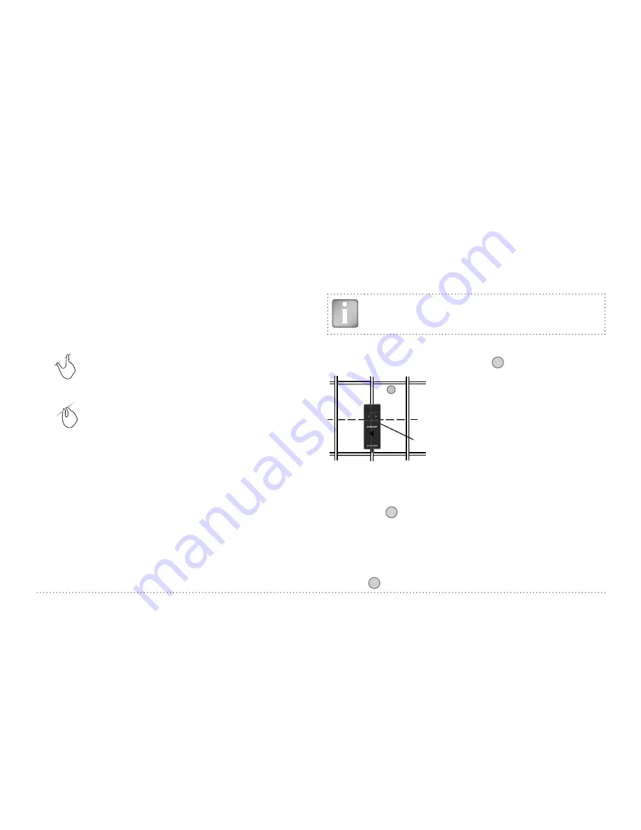
• Position the probe cart at the start line in an optimum position (see
Figure 9, the MC
C / D
at the mid line of the rebars running parallel to
the moving direction, both rectangles in
16
are of equal size).
Midpoint line
CL
16
MC C / D
Figure 9:
Optimal probe position
• Start with the measurement if the cursor is at the start line. If not per-
form a reset
8
.
• Move the probe cart with constant speed crosswise over the rebars,
not exceeding the maximum speed (speed bar 17 half filled in green).
• Above each rebar, when the red LED of MC
C / D
lights up, you may
measure the rebar diameter and on completion, it will be displayed in
blue. The measured diameter may be deleted within 5 seconds by tap-
ping on
6
.


