9
ready for use once again. This plant is built to have a protec-
tion level of IP 23 S, which means:
• That it is protected against the penetration of solid foreign
bodies with diameters in excess of Ø 12 mm.
• That it is protected against water spray hitting the surface
with an angle of incidence up to 60°.
• That the plant has been tested for withstanding harmful ef-
fects due to water getting in when the moving parts on the
equipment are moving.
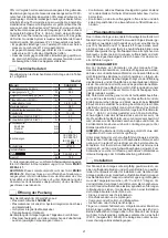
Technical data
The technical data for this equipment is summarized in the ta-
ble 1.
Table 1
Model
SHARK 25
Single-phase power supply 50/60 Hz
V
230
Mains supply: Z
max
(*)
Ω
0,32
Power input @ I
2
Max
kVA
5
Delayed fuse (I
2
@ 100%)
A
16
Power factor / cosφ
0,68 / 0,99
Maximum efficiency degree
η
0,80
Open circuit voltage (peak)
V
470
Current range
A
10 ÷ 25
Duty cycle @ 60% (40°C)
A
20
Duty cycle @ 35% (40°C)
A
25
Cutting capacity
recommended
maximum
severance
mm
mm
mm
6
8
10
Standards
IEC 60974-1
IEC 60974-7
IEC 60974-10
Insulation class
IP 23 S
Protection class
F
Dimensions
mm
540-425-220
Weight
kg
18,9
(*) Mains supply Z
max
: maximum impedance value allowed for
the grid according to the
EN/IEC 61000-3-11
standard.
WARNING: This equipment does not comply with EN/IEC
61000-3-12. If it is connected to a public low voltage system, it
is the responsibility of the installer or user of the equipment to
ensure, by consultation with the distribution network operator
if necessary, that the equipment may be connected.
Opening the packaging
The unit comprises the following main items:
•
SHARK 25
plasma cutting unit.
• Plasma torch with direct connection to the plant and spare
parts kit.
• Earth cable integrated into the plant.
• Trolley for transportation (optional).
On receipt of the unit, perform the following operations:
• Remove the plasma cutting unit and all relative accessories
and components from the packaging.
• Check that the plasma cutting unit is in good condition. If it is
not, inform your dealer immediately.
• Make sure that all the ventilation louvers are open and that
the airflow is not obstructed.
Plasma cutting
The cutting system used by this equipment is a low current sys-
tem that uses compressed air as its plasma generator as well
as for cooling. The air normally used is a mixture of 79% nitro-
gen and 21% oxygen. These two biatomic gasses have almost
identical enthalpy and form a highly energetic blend. The low
current also makes it possible to use torches with a low air ca-
pacity and moderate cutting speed, that are more suitable for
manual procedures.
CUTTING PARAMETERS
In analyzing the parameters that characterize manual plasma
cutting it is necessary to note that they depend on the material
to be cut, its thickness and the skill of the operator in following
the cutting line. Optimum speed depends largely on the skill of
the operator and amount of material to be cut and is achieved
when the fused material flows through the groove and is not
projected in the direction of the torch. If the latter occurs, cut-
ting speed has to be reduced.
In general, the parameters which influence cutting quality are
electrical voltage, compressed air capacity and the distance be-
tween the nozzle and the item, while with
SHARK 25
these are
reduced to the electrical voltage only (the augmented voltage
is obtained by incrementing the cutting current via the cutting
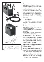
power regulation potentiometer (Pos. 1, Fig. A) which enables a
higher cutting speed or greater cutting depth) because the com-
pressed air supply is fixed and defined by the compressor, like
the distance between the nozzle and the item is fixed as cut-
ting is by contact only with both standard and prolonged items.
NOTE: The width of the cutting groove is usually about twice
the diameter of the hole in the hood.
Respect of the above recommendations ensures greatly re-
duced thermal alterations of the material due to cutting, that are
in any case always fewer than those caused by oxygen torches.
The thermally altered zone is in any case smaller than the zone
on which the weld is effective, so that in welding pieces that
have been cut by plasma it is not necessary to perform any
cleaning or grinding operations.
Installation
The place where the equipment is installed should be selected
with care so as to ensure satisfactory, safe use.
The user is responsible for installation and use of the equip-
ment according to the instructions provided by the manufac-
turer in this manual.
Temperatures must be between -25 °C e +55 °C. during trans-
portation and/or storage in stores.
Before installing the equipment the user should take into con-
sideration any possible electromagnetic problems in the work
area.
In particular, we recommend that the equipment not be installed
in the vicinity of:
• Signalling, control and telephone cables.
• Radiotelevision transmitters and receivers.
• Computers or controlling and measuring instrument.
• Safety and protection devices.
If the operator wears a pacemaker, hearing aid or other sim-
ilar device, he should consult his doctor before approaching
the equipment while it is running. The environment where the
equipment is installed must conform with the degree of protec-
tion of the chassis that is IP 23 S (IEC publication 60529). The
system is capable of working in environments where working
conditions are particularly hard.
This equipment cools water by forced circulation of air and must
therefore be positioned in such a way that the air can easily
be drawn in and expelled through the openings in the chassis.


