12
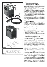
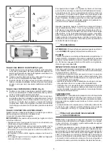
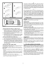
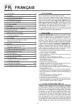
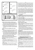
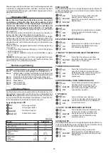
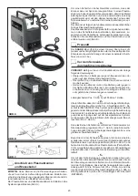
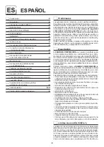
CUTTING FROM THE EDGE OF A PIECE (Fig. D)
A) Position the torch, in a vertical position, on the external
edge of the item to be cut. In particular cases of extinction
of the arc at the entrance of the item to be cut, increase
the angle between the item and the metal by 95°.
B) Begin cutting from the external edge of the item until the
arc has fully traversed the same.
C) During the cut the nozzle may be kept in direct contract
with the item being cut. Do not hold the pilot arc on in the
air to avoid wasteful wear on the electrode and nozzle.
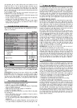
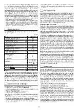
CUTTING FROM WITHIN AN ITEM (Fig. E)
A) Cut with the torch in an angular position with respect to the
item, the rotate slowly until perpendicular to the metal.
B) When sparks appear from the lower part of the item, this
indicates that the cutting arc has completely perforated the
item to be cut; The bore has been created and now the cut
can proceed. If the sparks and/or residues spray upwards,
this indicates that the torch is being moved too rapidly. Re-
duce cutting speed.
CUTTING WITH PROLONGED ITEMS
This technique is used to cut in poorly accessible positions such
as angles, hollows, channels, etc.
Consumables are used at a higher rate with this technique.
IMPORTANT: Precautions to be taken to cut correctly and ef-
ficaciously:
•
Always cut moving the torch gently to achieve a stable, pre-
cise cut.
•
Always cut moving the torch towards you which is simpler
than cutting while pushing or moving away from yourself.
•
Do not press or apply pressure to the torch during cutting
operations.
•
Always use a line of reference for straight cuts.
•
To execute circular cuts, we recommend application of the
specific compass (supplied upon request).
- 6 -
Completion of cutting operations. The compressor continues
to functions for some 25 seconds to consent the torch compo-
nents to cool after the arc is extinguished (“post flow” function).
The useful life of consumables is prolonged in this manner. Wait
for the air flow to cease before powering off the plant. During
this phase you may start a new cutting cycle: press the button
to restart the pilot arc.
- 7 -
When the operator powers the machine off, pressing the pow-
er supply switch (Pos. 7, Fig. A), the white LED continues to
indicate power supply on for several seconds, remaining lit
(Pos. 2, Fig. A) and the red LED plasma cutting cycle control
indicator (Pos. 3, Fig. A) flashes rapidly. (see paragraph “LED
Sequences” “POWERING OFF” section). During this period the
microprocessor verifying the correct function of each compo-
nent. Upon termination of this operation, the plant powers off.
Maintenance
WARNING: Before effecting any internal inspection of the
SHARK 25, interrupt the mains power supply.
SPARE PARTS
Original spares have been specifically designed for our equip-
ment. The use of spares that are not original may cause vari-
ations in the performance and reduce the safety level of the
equipment. We are not liable for damage due to use of spare
parts that are not original.
PLASMA CUTTING PLANT
As these systems are completely static except for the fan that
is, in any case, provided with self-lubricating bushes, only the
following operations are necessary:
• Periodic removal of accumulations of dirt and dust inside the
plant using compressed air. Do not point the jet of air directly
at the electrical parts as this could damage them.
• Periodical inspection for worn cables or loose connections
that could cause overheating.
• Make sure the air circuit is completely free of any impuri-
ties and that the connections are tight and free of any leaks.
In this connection, inspect the solenoid valve very carefully.
COMPRESSOR
SHARK 25
does not require an external compressed air sup-
ply as it contains an integrated air compressor which requires
efficacious periodic maintenance to correct and fully explete
its’ function.
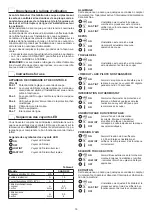
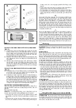
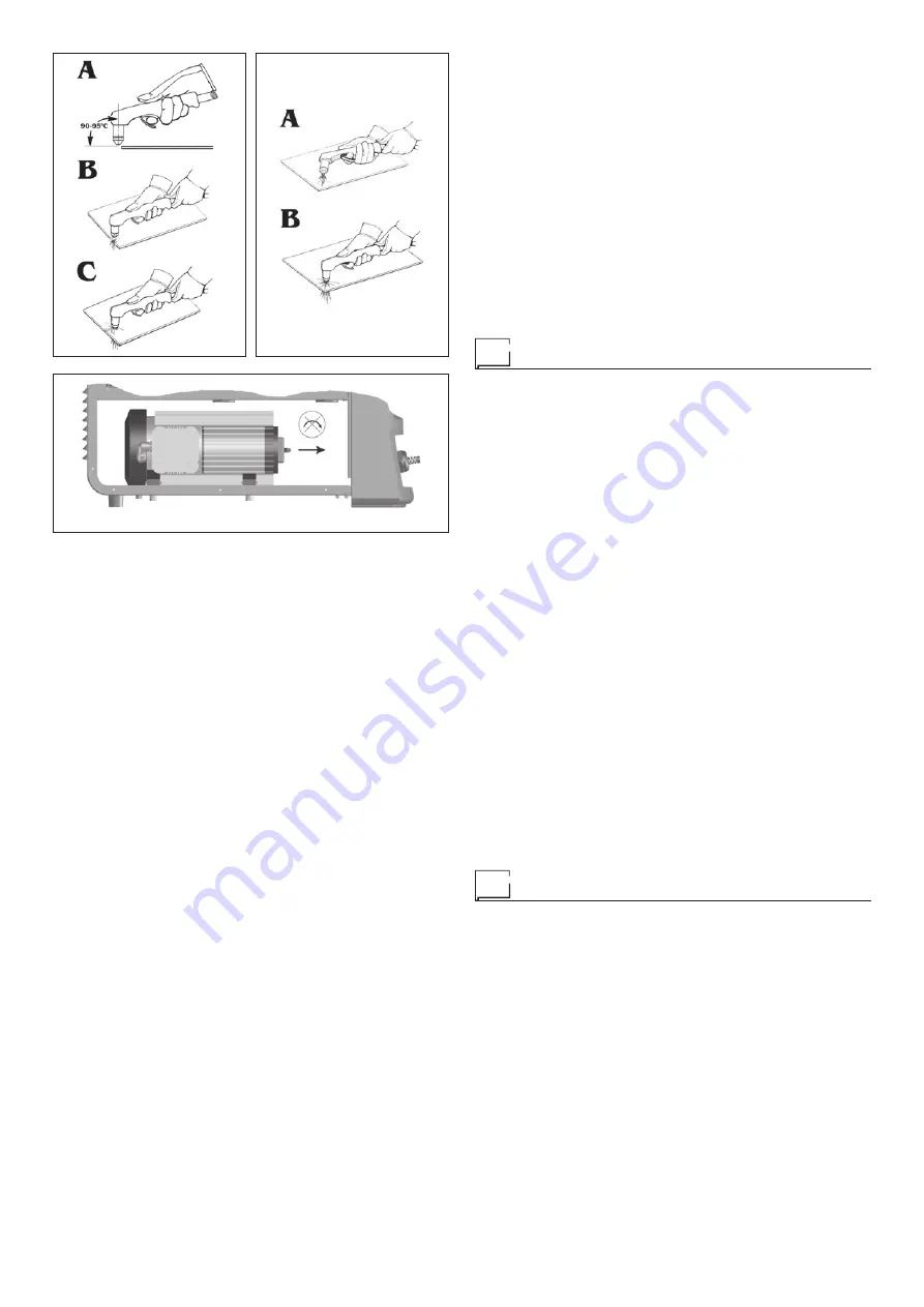
Compressor maintenance is limited to cleaning the air filter
which must be dismounted (pulling outwards but not rotating -
see Fig. F) and cleaned regularly.
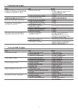
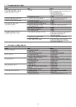
Possible problems and remedies
NOTE: Given the technical knowledge required to repair the
plasma cutting plant, in the case of breakage we recommend
contacting qualified personnel or our technical assistance ser-
vice.
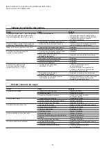
The 3 indicator LEDs, located on the
SHARK 25
rack panel,
enable, in most cases, identification of the cause of the fault.
We therefore recommend you check the LEDs to identify the
fault (see paragraph “LED Sequences”).
The faults possible in this plant are listed below with the proba-
ble causes, how to diagnose the same and how to solve prob-
lems rapidly and autonomously. If, however, the fault or problem
remains, contact our technical assistance service.
FIG. E
FIG. F
FIG. D


