8
ENGLISH
EN
Introduction
8
Description
8
Limits of use (IEC 60974-1)
8
Technical data
9
Opening the packaging
9
Plasma cutting
9
Installation
9
Connection to the mains supply
10
Instructions for use
10
LED Sequences
10
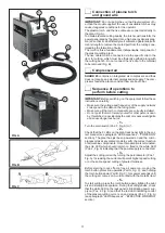
Connection of plasma torch and ground wire
11
Compressed air
11
Sequence of operations to perform before cutting
11
Maintenance
12
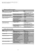
Possible problems and remedies
12
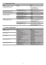
Troubleshooting table
13
Common cutting defects
13
Wiring diagram
80
Key to the electrical diagram
81
Colour key
82
Meaning of graphic symbols on machine
83
Spare parts list
84-85
Ordering spare parts
86
Introduction
Thank you for buying our product.
In order to get the best performance out of the plant and ensure
the maximum lifespan of its parts, the use and maintenance
instructions contained in this manual must be read and strictly
complied with, as well as
the safety instructions contained
in the relevant folder
. If repairs to the plant are required, we
recommend that our clients contact our service centre work-
shops, as they have the necessary equipment and personnel
that are specifically trained and constantly updated.
All our machines and equipment are constantly developed and
so changes may be made in terms of their construction and
features.
Description
SHARK 25 COMPRESSOR
single phase portable device for
plasma cutting with electronic microprocessor control, new IN-
VERTER technology, with incorporated compressor, this is the
ideal solution for manually cutting all metals and perforated
sheet. Inverter technology applied to plasma cutting guarantees
the best parameters with elevated cut quality in all circumstanc-
es. Powerful, compact, and light the
SHARK 25 COMPRES-
SOR
is ideal for panel beaters, light metalworkers, plumbers,
builders, installers and maintenance work of all kinds where a
compressed air supply is unavailable.
The main technical features are:
• Air compressor integrated into the plant. Thus, no external
compressed air supply necessary.
• Innovative practical design.
• Supporting structure in metal with front panel in special
shockproof material.
• Robust handle integrated into the chassis.
• Arc parameter control device for excellent cutting quality.
• Single-phase input.
• Reduced energy consumption.
• Stability of cutting parameters within ±10% of rated input volt-
age fluctuations.
• Faculty to grill cut and perforate sheet.
• Cutting operational cycle and alarm signals displayed with
lights.
• Plasma torch with ignition of pilot arc without high frequency.
• Accident prevention protection on the torch and plant com-
pliant with new international safety norms.
• Heat protection against overloads.
• Low air consumption (40 l/min).
• Long lasting consumables.
• Easy access to compressor air filter to permit better clean-
ing and thus improved reliability of the plasma cutting plant.
Limits of use (IEC 60974-1)
The use of plasma equipment for cutting is typically discontinu-
ous as it consists of periods of effective operation (cutting) and
rest periods (while the piece is being positioned, etc.). The size
of the equipment is suitable for safe use of max. nominal cur-
rent I2 for a working time that is 35% of the total time of use.
The regulations in effect stipulate that 10 minutes is the maxi-
mum total time of use. For the work cycle, 35% of that time is
considered. Exceeding the permitted work cycle triggers the
intervention of a thermal protector which protects the inter-
nal components of the plasma cutting plant against dangerous
overheating. The intervention of the thermal protection is indi-
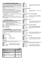
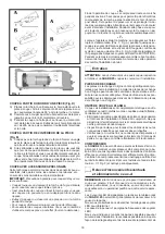
cated by powering on the yellow LED sited on the rack pan-
el (Pos. 4, Fig. A). After a few minutes the thermal protection
automatically resets, the yellow LED goes off and the plant is


