VersiStart i III
62
11.5
DC Brake with External Zero Speed Sensor
For loads which may vary between braking cycles, there are benefits in using an external zero-speed sensor to interface with the
VersiStart i III for brake shut-off. This control method ensures that the VersiStart i III braking will always shut off when the motor has
reached a standstill, thus avoiding unnecessary motor heating.
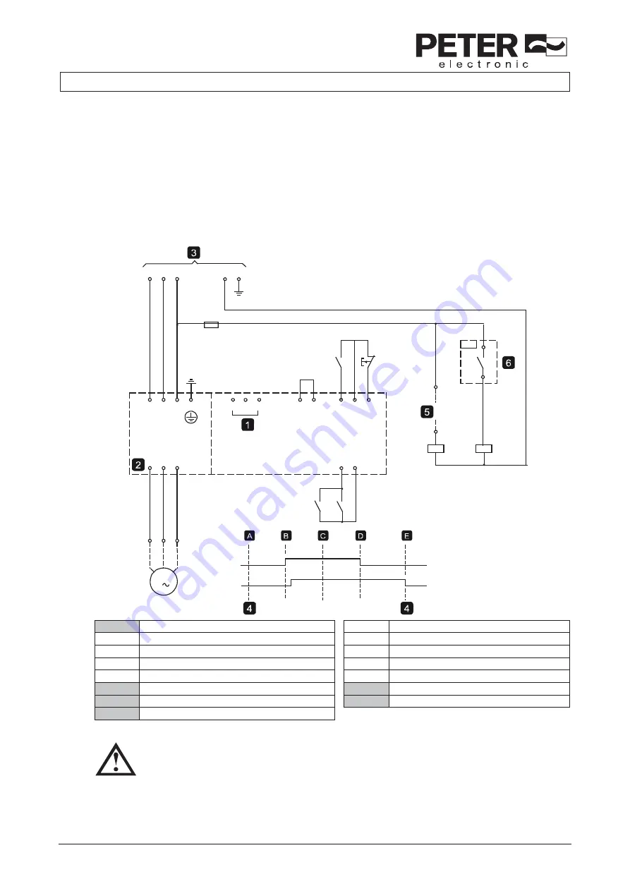
The following schematic diagram shows how you can use a zero-speed sensor with the VersiStart i III to turn the brake function off at
motor standstill. The zero-speed sensor (A2) is often referred to as an under-speed detector. Its internal contact is open at zero-speed
and closed at any speed above zero-speed. Once the motor has reached a standstill, 53, 55 will open and the starter will be disabled.
When the next start command is given (ie next application of K10), 53, 55 closes and the VersiStart i III is enabled.
The VersiStart i III must be operated in remote mode and parameter 6D Input A Function must be set to 'Starter Disable'.
12789.
C
-F1
L3
L2
L1
N
E
-K10
L1
L2
L3
E
T1
T2
T3
A5
A4
A6
54
55
56
57
58
53
55
-K10
-K11
-K10
-K11
T3
T2
T1
M
3
-K11
-K10
-A2
1
Control voltage (model dependent)
A
Off (Ready)
54, 55
Start
B
Start
56, 57
Stop
C
Run
58, 57
Reset
D
Stop
53, 55
Programmable input A (default = Motor Set Select)
E
Zero speed
2
Motor terminals
5
Start signal (2, 3, or 4-wire)
3
Three-phase supply
6
Zero speed sensor
4
Starter Disable (shown on starter display)
For details on configuring DC Brake, refer to Brake (page 35).
CAUTION
When using DC brake, the mains supply must be connected to the soft starter (input terminals L1, L2, L3) in positive phase
sequence and parameter 4B Phase Sequence must be set to Positive Only.


