


SINGLE MITRE SAW 50
ENG Rev 1
page 22
2.7.B
LADE LUBRICATION
(
COOLING
)
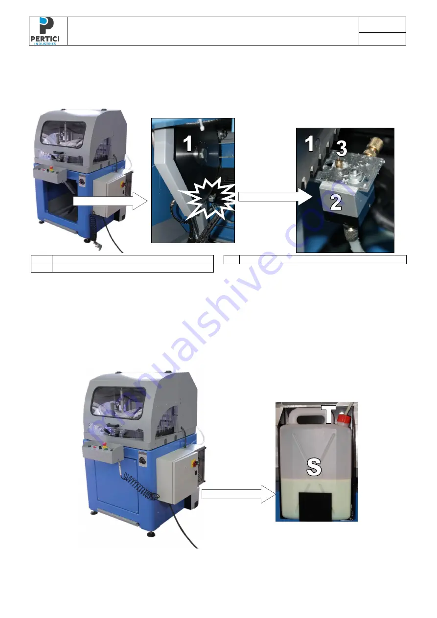
DEVICE
During cutting a special lubrorefrigerating liquid made by da PERTICI INDUSTRIES S.r.l. is
automatically nebulized on the blade to facilitate cutting.
1
BLADE
3
NOZZLE
2
LUBRICATION UNIT
Figure 18
– Blade lubrication unit
The tank of the lubricating liquid is put in the right side of the machine, respect to operator,
close to electric cabinet. This tank must be filled with a low-fat lubricating liquid solution: loosen
the tap (
T
), fill the tank (
S
) and tighten again the tap (
T
).
We strongly suggest to use Liquid Lubrificating PERTICI that beyond to be not obnoxious has
functional and chemical-physics characteristics properly created for the requested lubrication
and besides it is ecologically guaranteed.
Figure 19
– Lubricating liquid tank
Summary of Contents for Univer 50
Page 2: ......
Page 58: ...SINGLE MITRE SAW 50 ENG Rev 1 page 56...
Page 59: ...SINGLE MITRE SAW 50 ENG Rev 1 page 57 ANNEX 1 COMMERCIAL COMPONENTS...
Page 60: ...SINGLE MITRE SAW 50 ENG Rev 1 page 58 DRAWING OF COAXIAL UNIT...
Page 63: ...SINGLE MITRE SAW 50 ENG Rev 1 page 61 ANNEX 2 EXPLODED DRAWING OF MECHANICAL PARTS...
Page 64: ...SINGLE MITRE SAW 50 ENG Rev 1 page 62 DRAWINGS AND LISTS ARE TO BE UPDATED...