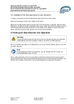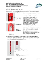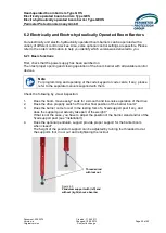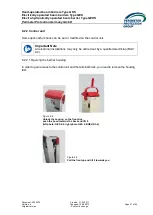
Hand-operated boom barriers Type GHS
Electrically operated boom barriers Type GES
Electro-hydraulically operated boom barrier Type GEHS
P
erimeter
P
rotection
G
ermany
G
mbH
Document: 2050274
Created: 11.04.2011
Version: a
Changed: 15.08.2013
Page 54 of 93
Original version
Subject to change
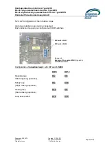
6.2.2.2.1 Basic setting for the induction loops
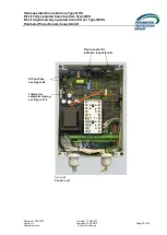
Warning
The DIP switches for the basic settings for the induction loops are located on the
plugged-in PCB of the loop detectors and not on the control PCB shown in
Figure 6.8. Induction loop 1 has 4 DIP switches (1-4) and, if present, induction
loop 2 also has 4 DIP switches (5-8).
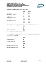
Setting the frequency
The operating frequency of the loop detector can be selected from two levels. The range of
permissible frequencies is from 30 to 130 kHz. The frequency depends on the loop
geometry, the number of loops, the loop wiring and the frequency level set with the DIP
switches. We recommend an operating range of 45 to 120 kHz.
Note
In order to determine the optimal frequency setting for the detector, you can use
our diagnostic device VEK FG2. On an LCD display, this diagnostic device
shows the frequency and dampening of the loops when a vehicle drives across
them.
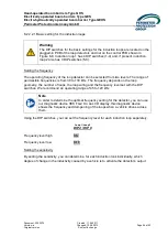
Using the DIP switches, you can set the frequency level for each induction loop separately.
Loop 1/ Loop 2
DIP 4 / DIP 8
Frequency level high
ON
Frequency level low
OFF
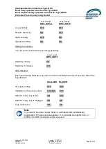
Setting the sensitivity
By setting the sensitivity, you can determine, for each induction look individually, which
degree of change in the inductivity caused by a vehicle is to activate the detector’s output.

