Hand-operated boom barriers Type GHS
Electrically operated boom barriers Type GES
Electro-hydraulically operated boom barrier Type GEHS
P
erimeter
P
rotection
G
ermany
G
mbH
Document: 2050274
Created: 11.04.2011
Version: a
Changed: 15.08.2013
Page 38 of 93
Original version
Subject to change
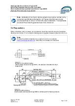
Please check:
o
Are the dimensions of the foundations correct?
o
Are the heights of the foundations correct in relation to the driveway?
o
Is the main foundation for the base plate of the barrier stand level? Small deviations
can be compensated for during installation.
o
If applicable, are the distances between the foundations for the base plate and that for
the fixed support post correct?
o
Are the conduits for the electrical wiring in the correct places?
o
Have the prescribed cables for the electro-mechanical barriers been properly laid in
the conduit?
o
Has the concrete cured completely?
o
Does the quality of the concrete correspond to B 25?
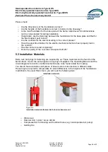
5.3 Installation Materials
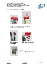
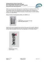
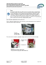
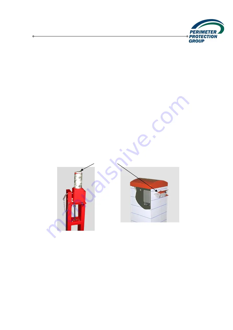
Bolts, nuts and plugs for fastening are supplied by us. These materials can be found on the
barrier-boom mount; the same applies to any keys if supplied. The Operating Manual and the
circuit diagrams for electro-mechanical barriers are to be found inside the housing.
You should have available small pieces of sheet metal or steel section in different sizes.
These may be required to compensate for small differences in the heights of the foundations.
In addition to the usual fitter’s tools, you will need the following tools:
o
Water level
o
Hammer drill, 12-mm
stone drill bit
o
Compressed air for blowing out the drilled holes (e.g. hand-operated air pump)
o
Guiding line
Figure 5.3
Installation materials fastened to the barrier-boom mount
Installation materials

