Hand-operated boom barriers Type GHS
Electrically operated boom barriers Type GES
Electro-hydraulically operated boom barrier Type GEHS
P
erimeter
P
rotection
G
ermany
G
mbH
Document: 2050274
Created: 11.04.2011
Version: a
Changed: 15.08.2013
Page 47 of 93
Original version
Subject to change
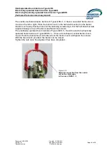
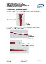
The threaded rod can be adjusted by means of the locknut. Because of its shorter threaded
rod, the pendulum support fitted with the shock absorber has a telescope-type length
adjustment for rough height setting.
5.7 Installation of the Fixed Support Post
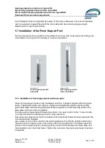
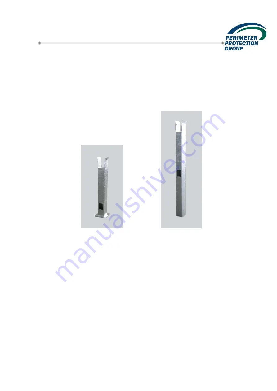
The fixed support post is available in two different versions: with a base plate for bolting onto
a foundation or as a post for mounting in a sleeve foundation.
5.7.1 Installation of fixed support post with base plate
Place the fixed support post on the foundation so that is it properly aligned with the barrier
boom. If applicable, make sure that any cables are threaded through the opening of the
post’s base plate without being damaged. Mark the positions of the fastening holes in the
base plate on the concrete foundation.
The base plate is fastened with fastening anchors. You need to drill 12-mm
holes into the
concrete and insert the fastening anchors using a hammer.
Now place the support post on the foundation and temporarily fasten the base plate with the
nuts and washers supplied.
Use a water level to check, whether the fixed support post is perfectly upright and whether
the barrier boom properly rests in the resting fork of the support post. If needed, adjust the
position of the support post by inserting pieces of sheet metal between the base plate and
the foundation near the drilled holes. Tighten the nuts once the alignment process has been
completed.
Figure 5.21
Fixed support post with
base plate
Figure 5.22
Fixed support post for
sleeve foundation

