background image

52

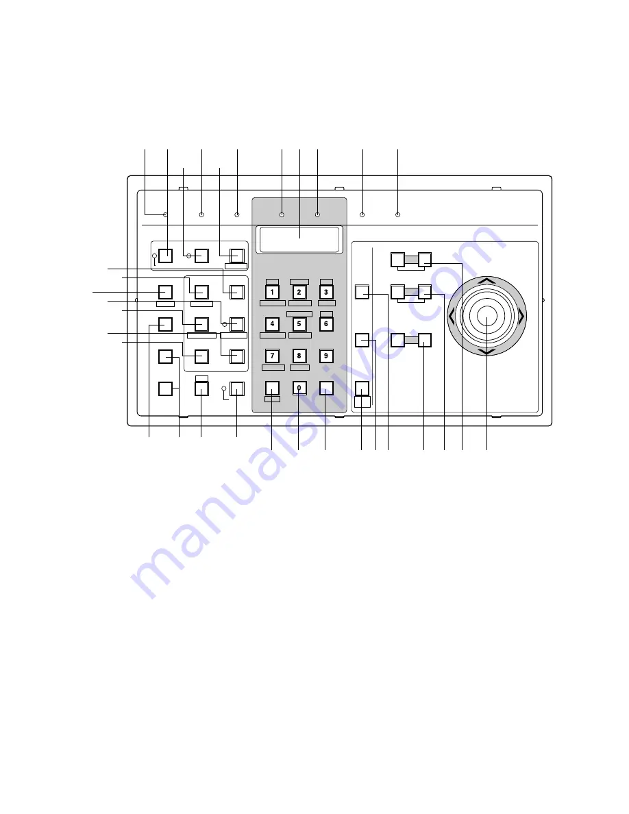
WV-CU350 System Controller

Appearance

The System controller comes with three templates for use with the Matrix Switcher or Video Multiplexer. Make sure to place the
template for the Matrix Switcher (System 850) on the controller.

Front View

q

Operate indicator (OPERATE)

Is on (green) while the controller’s power is turned on.

w

Link indicator (LINK)

Is on (green) when communication is established with
the Main CPU.

e

Alarm indicator (ALARM)

Lights (red) to indicate that an alarm condition exists.
To turn off the indicator, select the alarm by pressing
the Numeric and ALARM buttons, then press the RESET
button.

r

Monitor indicator (MONITOR)

Is on (orange) when the monitor number is displayed on
the LED Display.

t

LED Display

Displays the number of monitors and cameras currently
controlled.
It also displays numeric input and error status, etc.

y

Camera indicator (CAMERA)

Is on (orange) when the camera number is displayed
on the LED Display.

u

Busy indicator (BUSY)

Lights up (red) when you attempt to control a monitor
(or camera) that is already used by a higher priority
operator, or when the higher priority operator selects
the camera or monitor you are currently operating.
Operations from the System Controller are disabled
until this indicator goes off.

OPERATE

LINK

ALARM

MONITOR

CAMERA

BUSY

PROHIBITED

PROGRAM

PRESET

IRIS

System Controller WV-CU

350

For Matrix Switcher (System 850)

OPEN

CLOSE

AUTO IRIS

CALL

PRESET

AUX1 OFF

ALM S

CAM ID

T&D

AUX1 ON

VLD S

RESET

ACK

NEXT

PREV

S-CTL ID

STOP

PAUSE

CAM MENU ON

CAM MENU OFF

TOUR

SEQ

GROUP

SEQ

MONITOR

LOCK

OSD SERVICE

CAM FUNC

OSD

ALARM

DISARM

ALL RESET

OPE ID

GROUP PRESET

LOG OUT

F1

F2

GEN

WIPER

SYS S

AUX2 OFF

ALM H

MON STATUS

AUX2 ON

VDL H

ALL

SHIFT

BLK

EXIT

CLEAR

(ESC)

DEF OFF

DEF ON

CAMERA

(ENTER)

AUTO

PAN

FOCUS

FAR

NEAR

AUTO FOCUS

ZOOM

DOWN

UP

R

L

TELE

WIDE

q

w

e

r

y

u

t

i

!6

!7

@2

@4

@5

@8

@6

@7

@3

#1

@9

#0

#2

!8

@1

@0

o

!0

!1

!2

!3

!4

!5

!9

Summary of Contents for System 850

Page 1: ...ore attempting to connect or operate this product please read these instructions carefully and save this manual for future use System 850 Matrix Switcher Operating Instructions System Controller WV CU 850 ...

Page 2: ... the pres ence of uninsulated dangerous voltage within the product s enclosure that may be of sufficient magnitude to constitute a risk of electric shock to persons The exclamation point within an equilat eral triangle is intended to alert the user to the presence of important operating and maintenance servicing instructions in the literature accompanying the appli ance CAUTION TO REDUCE THE RISK ...

Page 3: ... WV CU850 System Controller 47 WV CU350 System Controller 52 INSTALLATIONS AND SYSTEM CONNECTIONS 57 INSTALLATIONS 58 INSTALLATION OF SYSTEM COMPONENTS 58 BOARD SELECTION FOR SYSTEM EXPANSION 62 SYSTEM CONNECTIONS 70 OPERATING PROCEDURE with WV CU850 77 Log in and Log out 78 Monitor and Camera Selection 79 Display Setting for Controller 81 Controlling Camera Site Accessories 82 Camera Function Con...

Page 4: ...128 Ethernet system con trollers Moreover its flexible scalable and high density modular system architecture allows for easy expansion The System 850 is controlled and programmed via an Ethernet or RS 485 port by standard enhanced or high speed CPUs The standard CPU is designed for systems having up to 512 inputs and 64 outputs and the enhanced CPU for systems having up to 1 024 inputs and 256 out...

Page 5: ...onnel for maintenance Handle the appliance with care Do not strike or shake as this may damage the appli ance Do not expose the appliance to water or moisture nor try to operate it in wet areas Take immediate action if the appliance becomes wet Turn the power off and refer servicing to qualified ser vice personnel Moisture may damage the appliance and also cause electric shock Do not use strong or...

Page 6: ...FF AUX2 ON DEFAULT FOCUS ALARM ACK RESET ALL RESET ARM GROUP PRESET PREV S CTL ID OPE ID NEXT GROUP SEQ PAUSE STOP TOUR SEQ REV RUN FWD RUN OSD F 1 F 2 F 3 CMENU OFF F 4 CMENU ON F 5 F 6 CLOSE IRIS WIPER OPEN NEAR FAR UP BUSY ACK LOCK CAMERA INFORMATION MONITOR ALARM LINK OPERATE DOWN R L WIDE TELE AUTO FOCUS ZOOM MONITOR LOCK LOGOUT AUX1 OFF AUX1 ON CALL PRESET PGM PRESET CAM POSI DIGITAL OUT CAM...

Page 7: ... inputs and outputs The on screen display cage MXOSD provides A maximum of 128 monitor output in a Card Cage Display of monitor number monitor status camera title and clock Main CPU Central Processing Unit The Main CPU controls the functions of the entire sys tem There are three types of CPUs a Standard an Enhanced and a High Speed custom made configu ration CPU each of which incorporates a high p...

Page 8: ...9 DETAILED PRODUCT DESCRIPTION ...

Page 9: ...atrix Switcher It is provided with a power supply for the boards installed and a Local CPU board to control boards in the cage Appearance DO NOTOPEN RISK OF ELECTRICSHOCK SIGNAL GND SIGNAL GND RS 232C CAUTION ATTENTION NE PAS OUVRIR RISQUE DE CHOCS ELECTROUES VS VD IN OUT VD OUT ETHERNET AC IN 850 u y t r e w Rear View OPERATE Matrix Switcher WJ SX 850 q Front View ...

Page 10: ...k signal e VS VD Output Connector VS VD OUT Outputs either the VD Vertical Drive pulse or the VS Video Sync signal for synchronizing other system components Note The input at the VS VD Input Connector is looped through to this output These inputs and outputs are connected internally r VD Output Connector VD OUT Outputs VD Vertical Drive pulses for synchronizing other system components Notes The in...

Page 11: ...ler 2 Extract the Local CPU board by raising up the card puller 1 2 3 4 ON 1 2 3 4 ON SW8 SW4 1 2 3 4 ON SW13 SW7 SW7 VD VS SW11 SW12 SW10 SW9 SW11 SH F E2P CPU BOARD 0 1 2 3 4 5 6 789A B C D E F SW1 SW3 SW2 Hold this board only by its edges Otherwise components on the board may be damaged by static electricity Caution SW1 Factory use only SW3 LCPU Reset Switch SW2 Card Cage Reset Switch ...

Page 12: ... 9 9 9 3 4 1 2 3 4 1 2 3 4 1 2 3 4 SW10 SW9 Designate further cage numbers referring to the above address table Cage numbers are available up to 1 024 4 Set switch SW7 on the board to select either VD or VS for the Sync input signal if applicable The factory default setting is VD SW7 VS VD 5 Confirm that switch SW11 on the board is set to E2P position SW11 SH F E2P 89 A B C D E F 0 1 2 3 4 5 6 7 3...

Page 13: ... OFF ON OFF 2 3 4 7 Place the board into the CPU slot in the front of the cage by sliding it along the board guide DIP SW8 1 4 OFF ON PROM Mode MAC Address Write enable Mode Normal Mode Normal Mode 6 Confirm that switches SW4 SW8 and SW13 on the board are set as follows 1 2 3 4 ON ...

Page 14: ... B W composite video signal from a camera In addition the VD2 signal for synchronizing the vertical timing of the cameras and data to control camera site devices are multiplexed through this connector w Video Output Port VIDEO OUT The video signal connected to the Camera Input Connector CAMERA IN is present at this port The camera control data multiplexed on the video signal is not available at th...

Page 15: ...he camera input board number as shown in the following table The factory default setting is Board Number 1 00 Board No Camera Input SW Positions SW5 SW4 1 2 3 4 5 6 7 8 9 10 11 12 13 14 15 16 0 0 0 0 0 0 0 0 0 0 0 0 0 0 0 0 0 1 2 3 4 5 6 7 8 9 A B C D E F 1 8 9 16 17 24 25 32 33 40 41 48 49 56 57 64 65 72 73 80 81 88 89 96 97 104 105 112 113 120 121 128 89 A B C D E F 0 1 2 3 4 5 6 7 Board Setting...

Page 16: ...haracter Board is installed on the Camera Input Board position jumper connectors CN103 CN203 CN303 CN403 CN503 CN603 CN703 and CN803 on the board as shown below The factory default setting is positions 1 and 2 CN101 1 3 2 4 CN101 Multiplexed Camera Default Setting Others 1 3 2 4 CN103 3 1 CN103 Default Setting Installed Character Board 1 3 ON 1 Character display without camera input 2 No retry mod...

Page 17: ...face The WJ PB85D01 Character Board is an optional board installed on the WJ PB85X08 Camera Input Board to enable display of the time and date and camera number through the Video Output Port on the Camera Input Board Appearance CN2 CN1 ...

Page 18: ...nnected to the Through I O Port w Through I O Port IN OUT This port accepts the composite video output from the associated video equipment or pro vides the looped through video outputs connected to the Through I O Connectors 1 2 3 4 5 6 7 8 IN OUT IN OUT THRU q w 17 16 15 14 5 4 3 2 1 20 19 18 8 6 23 22 21 11 10 9 7 25 24 13 12 Pin No Designation 25 24 23 22 21 20 19 18 17 16 15 14 VIDEO 1 VIDEO 2...

Page 19: ...d Setting Before installing this board the following settings should be made by qualified service personnel or system installers 1 Confirm that jumper connectors CN101 CN201 CN301 CN401 CN501 CN601 CN701 and CN801 on the board are positioned as shown below CN101 1 2 ...

Page 20: ...W Selection Switch Full Duplex Half Duplex GND Ground Connected to each channel and common ground q Data Connectors TA TB RA RB G 1 8 These connectors are used to exchange control data with the camera site devices For con nection use a data grade shielded 4 wire twisted pair cable suitable for RS 485 communica tion q RS485 A T B A R B G A T B A R B G A T B A R B G A T B A R B G 1 2 3 4 A T B A R B...

Page 21: ...701 SW802 SW801 4LINE 2LINE TERM ON TERM OFF Reset Switch Board No Data I O SW Positions SW2 SW1 1 2 3 4 5 6 7 8 9 10 11 12 13 14 15 16 0 0 0 0 0 0 0 0 0 0 0 0 0 0 0 0 0 1 2 3 4 5 6 7 8 9 A B C D E F 1 8 9 16 17 24 25 32 33 40 41 48 49 56 57 64 65 72 73 80 81 88 89 96 97 104 105 112 113 120 121 128 1 Set switches SW1 and SW2 on the board to designate the RS 485 data board number as shown in the fo...

Page 22: ... SW202 SW302 SW402 SW502 SW602 SW702 and SW802 on the board to choose either Full Duplex 4 LINE or Half Duplex 2 LINE com munication lines as shown below The factory default settings are Full Duplex 4 LINE 4LINE 2LINE 4 Confirm that switches SW3 on the board are set to the positions as shown below 1 2 3 4 OFF DIP ON 1 One way mode 2 No retry mode 3 Reserved 4 Reserved OFF Handshake mode 3 retries ...

Page 23: ...ation 25 24 23 22 21 20 19 18 17 16 15 14 Pin No Designation 13 12 11 10 9 8 7 6 5 4 3 2 1 Ground Ground Ground Ground Ground Ground Ground Ground Ground Ground Ground Ground Ground w Video Output Port VIDEO OUT 1 2 The video signal connected to the VIDEO IN port is looped through to these ports If video output extensions are required connect between these ports and the VIDEO IN ports on the WJ PB...

Page 24: ... 0 0 0 0 0 0 0 0 0 0 0 0 1 2 3 4 5 6 7 8 9 A B C D E F 1 16 17 32 33 48 49 64 65 80 81 96 97 112 113 128 129 144 145 160 161 176 177 192 193 208 209 224 225 240 241 256 1 Set switches SW902 and SW903 on the board to designate the crosspoint input board number as shown in the following table The factory default setting is Board Number 1 00 89 A B C D E F 0 1 2 3 4 5 6 7 Board Setting Before install...

Page 25: ...UT 3 Crosspoint input for 1 channel The jumper connector positions designate the following functions Video Input Termination 5 and 6 Closed 75 Ω termination 5 and 6 Open High Z impedance termination Clamping Circuit 8 and 10 7 and 9 Closed Off 7 and 8 9 and 10 Closed On Video Output Mode 1 and 2 3 and 4 Closed Wired Loop Through 1 and 3 2 and 4 Closed Buffered Through For further details on settin...

Page 26: ...is clamped before sending it out to the board circuit to adjust the black level to that of another input signal The above are the factory default settings Middle stage cage Other than the initial and final stages No clamping circuit is required because the signal input has already been clamped at the initial stage and buffered by the DC amplifier To transfer the same input signal to the next stage...

Page 27: ...ut signal to another cage The signal output is clamped before sending it out to the board circuit to adjust the black level to that of another input signal Middle stage cage Position the jumper connectors as for the initial stage cage Final stage cage Position the jumper connectors as for the initial stage cage When the jumper connectors are in this position there is no 75 Ω drive for VIDEO OUT If...

Page 28: ...18 17 16 15 14 Pin No Designation 13 12 11 10 9 8 7 6 5 4 3 2 1 Ground Ground Ground Ground Ground Ground Ground Ground Ground Ground Ground Ground Ground 17 16 15 14 5 4 3 2 1 20 19 18 8 6 23 22 21 11 10 9 7 25 24 13 12 2 VIDEO 9 VIDEO 10 VIDEO 11 VIDEO 12 VIDEO 13 VIDEO 14 VIDEO 15 VIDEO 16 Not Used Not Used Not Used Not Used Pin No Designation 25 24 23 22 21 20 19 18 17 16 15 14 Pin No Designat...

Page 29: ...itch Board No VIDEO IN OUT SW Positions SW703 SW702 1 2 0 0 0 1 1 16 17 32 1 Set switches SW702 and 703 on the board to designate the crosspoint output board number as shown in the following table The factory default setting is Board Number 1 00 89 A B C D E F 0 1 2 3 4 5 6 7 Board Setting Before installing this board the following settings should be made by qualified service personnel or system i...

Page 30: ...ec Output Spec MODE A MODE B MODE C MODE D 75 Ω Termination 75 Ω Termination Hi Z Termination 150 Ω Termination 75 Ω Buffered Output 75 Ω with 150 Ω Termination Buffered Output Wired Loop Through 75 Ω Buffered Output For further details on settings refer to the appendix 3 When two crosspoint output boards are installed in a Crosspoint Cage MXSW position jumper connectors CN217 CN218 CN219 CN220 CN...

Page 31: ...f this cage is turned on and S of other cages is turned off In order to secure 75 Ω for signal send out from the initial stage a 150 Ω termination is provided for the 75 Ω impedance drive and another 150 Ω termina tion is provided at the final stage Middle stage cage Other than the initial and final stages When an input of this cage is selected S of this cage is turned on and S of other cages is t...

Page 32: ...deo Input Port VIDEO IN Accepts the video signal from the VIDEO OUT Port on the WJ PB85M16 Crosspoint Output Board of the Crosspoint Card cage MXSW 1 2 3 4 5 6 7 8 MONITOR OUT VIDEO IN OSD q w 17 16 15 14 5 4 3 2 1 20 19 18 8 6 23 22 21 11 10 9 7 25 24 13 12 Pin No Designation 25 24 23 22 21 20 19 18 17 16 15 14 VIDEO 1 VIDEO 2 VIDEO 3 VIDEO 4 VIDEO 5 VIDEO 6 VIDEO 7 VIDEO 8 Not used Not used Not ...

Page 33: ... 105 112 113 120 121 128 Board Setting Before installing this board the following settings should be made by qualified service personnel or system installers SW3 SW2 SW1 SW5 OFF 1 2 3 4 0 1 2 3 4 5 6 789A B C D E F Reset Switch 1 Set switches SW1 and SW2 on the board to designate the on screen display board number as shown in the following table The factory default setting is Board Number 1 00 89 ...

Page 34: ...35 1 Switch Positions 2 Confirm that switches SW3 on the board are set to the OFF position as shown below SW3 OFF 1 2 3 4 4 3 2 Switch Number OFF OFF OFF OFF SW3 ...

Page 35: ...m 3 Alarm 2 Alarm 1 23 22 21 20 5 4 3 2 1 26 25 24 8 6 29 28 27 11 10 9 7 32 31 30 14 13 12 33 15 36 35 34 18 37 19 17 16 WJ PB85A32 Alarm Input Board Preface The WJ PB85A32 Alarm Input Board is an optional board for expanding the capabilities of the System 850 Matrix Switcher It transmits a received alarm signal to the CPU Central Processing Unit via Ethernet to activate the assigned alarm event ...

Page 36: ... H 1 9 17 25 8 16 24 32 ON Board No Alarm Input SW Positions SW2 SW1 1 2 3 4 5 6 7 8 9 10 11 12 13 14 15 16 0 0 0 0 0 0 0 0 0 0 0 0 0 0 0 0 0 1 2 3 4 5 6 7 8 9 A B C D E F 1 32 33 64 65 96 97 128 129 160 161 192 193 224 225 256 257 288 289 320 321 352 353 384 385 416 417 448 449 480 481 512 1 Set switches SW1 and SW2 on the board to designate the alarm input board number as shown in the following ...

Page 37: ...Closed N C OFF Normally Open N O The factory default settings are OFF 1 2 3 4 5 6 7 8 ON SW4 ON OFF CH1 8 3 If this board is used for Alarm Output set switches SW3 on the board as follows ON Output mode OFF Input mode The factory default settings are OFF 1 2 3 4 SW3 OFF ON C H 1 9 17 25 8 16 24 32 ON ...

Page 38: ...Port 1 32 This port supplies alarm output to the actuators connected to it through either Normally Open N O or Normally Closed N C contacts on this board 1 32 ALARM OUT q 23 22 21 20 5 4 3 2 1 26 25 24 8 6 29 28 27 11 10 9 7 32 31 30 14 13 12 33 15 36 35 34 18 37 19 17 16 Ground Ground Not used Not used Not used Alarm 32 Alarm 31 Alarm 30 Alarm 29 Alarm 28 Alarm 27 Alarm 26 Alarm 25 Alarm 24 Alarm...

Page 39: ...3 CN4 1 3 NOR INV Polarity Reset Switch Board No Alarm Output SW Positions SW2 SW1 1 2 3 4 5 6 7 8 9 10 11 12 13 14 15 16 0 0 0 0 0 0 0 0 0 0 0 0 0 0 0 0 0 1 2 3 4 5 6 7 8 9 A B C D E F 1 32 33 64 65 96 97 128 129 160 161 192 193 224 225 256 257 288 289 320 321 352 353 384 385 416 417 448 449 480 481 512 1 Set switches SW1 and SW2 on the board to designate the alarm output board number as shown in...

Page 40: ...onfirm that the jumper connectors are positioned at Ground GND as shown below The factory default settings are Normally Open N O 21 22 23 24 21 22 23 24 NO NC GND COM CN210 Normally Open N O Default Setting Normally Closed N C Ground GND Default Setting 3 Confirm that the jumper connector CN4 on the board is positioned on 1 and 2 This setting lets you select the output polarity CN4 1 3 NOR INV Pol...

Page 41: ...on RESET The RESET button is recessed inside the front panel hole to the right of the OPERATE indicator Press this button when the CPU rejects control from outboard equipment e Fan Alarm Indicator FAN ALARM Indicates the cooling fan status This LED lights when a temperature rise in the CPU is detected Turn the power off and refer servicing to qualified service personnel r HDD Hard Disk Drive Indic...

Page 42: ...ANDALONE position 1 Parallel Port PARALLEL This port is used to connect to the WJ MPS850 CPU Switch Unit for a redundant system 2 Cooling Fan Unit Prevents the temperature of the CPU from rising Do not block the ventilation opening on the cover 3 Fuse Holder 4 AC Inlet Socket AC IN Plug the power cord supplied as a standard accesso ry into this socket and connect it to an AC outlet ...

Page 43: ... WJ MPU855 CPU is turned on Note The power switch of the CPU is located under neath the front panel Remove the front panel by removing two screws on the panel w Reset Button RESET The RESET button is recessed inside the front panel hole to the right of the OPERATE indicator Press this button when the CPU rejects control from outboard equipment e Fan Alarm Indicator FAN ALARM Indicates the cooling ...

Page 44: ...ng is NO 0 Mode Selector SATELLITE MODE Always keep in STANDALONE position 1 Parallel Port PARALLEL This port is used to connect to the WJ MPS850 CPU Switch Unit for a redundant system 2 Cooling Fan Unit Prevents the temperature of the CPU from rising Do not block the ventilation opening on the cover 3 Fuse Holder 4 AC Inlet Socket AC IN Plug the power cord supplied as a standard accesso ry into t...

Page 45: ...g between cages Cables are supplied in seven different lengths Appearance 1 0 m 1 0 m Model Number Cable Length WJ CA85L05 0 5 m 1 6 ft WJ CA85L10 1 0 m 3 3 ft WJ CA85L15 1 5 m 4 9 ft WJ CA85L20 2 0 m 6 6 ft WJ CA85L25 2 5 m 8 2 ft WJ CA85L30 3 0 m 9 8 ft WJ CA85L50 5 0 m 16 4 ft 13 1 1 25 14 13 25 14 ...

Page 46: ...erator or when a higher priority operator selects the monitor you are currently operating Operations from the System Controller are disabled until this indicator goes off e Monitor LED Display MONITOR Displays the Monitor Number currently controlled r Monitor Lock Indicator LOCK Lights red to indicate that the currently selected moni tor is priority locked and retains control of a monitor by an op...

Page 47: ... F4 while holding down the SHIFT key will open the Camera Menu on the active monitor screen CMENU ON F5 Reserved for future use F6 Pressing this key will select the mode for control ling selected camera function CAM FUNC 65 Joystick Controller L R UP DOWN The joystick is used to manually operate the PAN Tilt Head or move the cursor in the Camera Menu on the active monitor screen UP Upward DOWN Dow...

Page 48: ...he system such as the camera and monitor number sequence number preset position etc 9 Shift key SHIFT Pressing this key in combination with keys to which special functions have been assigned will activate these functions 0 Next key NEXT When a Tour Sequence running in forward direction has been paused with the Pause key pressing this key will move the sequence one frame to the next step in for war...

Page 49: ...y programmed Group Preset function Pressing this key while holding down the SHIFT key will display the Operator ID on the LCD display OPE ID 8 Group Sequence key GROUP SEQ This key in combination with the Numeric keys is used to run a Group Sequence forward on the assigned mon itors 9 Tour Sequence key TOUR SEQ This key in combination with the Numeric and FWD RUN REV RUN keys is used to run a Tour...

Page 50: ...d camera LED display 4 LCD Brightness Control LCD BRIGHT Adjusts the back light brightness of the LCD 5 LCD Contrast Control LCD CONTRAST Adjusts the contrast of the characters displayed on the LCD 6 Ethernet Port ETHERNET Exchanges control data with the Central Processing Unit CPU via Ethernet 7 Data Port DATA Reserved for future use 8 RS 232C Port RS 232C This port is used only for factory tests...

Page 51: ...tc y Camera indicator CAMERA Is on orange when the camera number is displayed on the LED Display u Busy indicator BUSY Lights up red when you attempt to control a monitor or camera that is already used by a higher priority operator or when the higher priority operator selects the camera or monitor you are currently operating Operations from the System Controller are disabled until this indicator g...

Page 52: ...own the SHIFT button will activate the auto panning function of the selected camera AUTO PAN 6 Clear Escape button CLEAR ESC Clear This button is used to clear numeric input from the LED Display Escape This button is used to escape from the current ly highlighted selection and return to the previous page of the Camera Menu This button is also used to exit from alarm selecting mode to normal operat...

Page 53: ...s button is used to pause a Tour or Group Sequence that is being run on the active monitor Pressing PAUSE while holding down the SHIFT button will close the Camera Menu on the active monitor The STOP indicator will go off CAM MENU OFF 6 Tour Sequence button TOUR SEQ This button in combination with the Numeric buttons is used to run a Tour Sequence on the active monitor Pressing TOUR SEQ will resta...

Page 54: ... System Controller Set the switches to the required positions shown below Caution Turn the controller s power off when changing the DIP switch setting 2 Data Output Port DATA OUT Exchanges control data with the Central Processing Unit CPU 3 DC 9V Input Jack DC 9V IN This jack is used to connect the AC Adapter supplied with the System Controller ...

Page 55: ...57 INSTALLATIONS AND SYSTEM CONNECTIONS ...

Page 56: ... Camera Input Board follow the procedure shown below 1 Position jumper connectors CN103 CN203 CN303 CN403 CN503 CN603 CN703 and CN803 on the Camera Input board as shown below CN103 1 3 2 Insert the connectors of the Character board into the specified connectors CN102 CN202 CN302 CN402 CN502 CN602 CN702 and CN802 on the Camera Input board 3 Place the Character board on the Camera Input board and pl...

Page 57: ...X850 Card cage 4 Place the Boards into the specified positions in the front or rear of the Cage by sliding them along the board guides as shown below 5 Make sure to push in the Boards until they are seated firmly 6 Secure the rear board by tightening the two screws on the board Board Tighten screws Tighten screws Rear panel Rear panel Tighten screws 7 Close open spaces on the rear of the Cage with...

Page 58: ...alm rest located on the front of the System Controller by removing two screws 3 Place the Rack Mounting Brackets on both sides of the System Controller and tighten with the four supplied screws 4 Install the System Controller with Rack Mounting Brackets in the rack by using four screws not included Remove screws Tighten screws Rack Mounting Bracket Palm rest Side Panel Rack Mounting Screws Rack Mo...

Page 59: ...he rear of the unit to the rack using additional mounting brackets procured locally WJ MPU850 Central Processing Unit WJ MPU855 Central Processing Unit Mounting into the Rack 1 Remove the four rubber feet by removing four screws from the bottom of the CPU 2 Install the CPU in the rack securing it with four screws not included Control Processing Unit WJ MPU 850 Rack Mounting Screws Cautions The coo...

Page 60: ...depending on the number of camera inputs and monitor out puts required Front View 1 2 3 4 5 6 7 8 9 10 11 12 13 14 15 16 17 18 CPU DO NOTOPEN RISK OF ELECTRICSHOCK SIGNAL GND SIGNAL GND RS 232C CAUTION ATTENTION NE PAS OUVRIR RISQUE DE CHOCS ELECTROUES VS VD IN OUT VD OUT ETHERNET AC IN 18 17 16 15 14 13 12 11 10 9 8 7 6 5 4 3 2 1 Rear View ...

Page 61: ...A IN VIDEO OUT CAMERA 1 2 3 4 5 6 7 8 CAMERA IN VIDEO OUT CAMERA 1 2 3 4 5 6 7 8 CAMERA IN VIDEO OUT CAMERA 1 2 3 4 5 6 7 8 CAMERA IN VIDEO OUT CAMERA 1 2 3 4 5 6 7 8 CAMERA IN VIDEO OUT CAMERA 1 2 3 4 5 6 7 8 CAMERA IN VIDEO OUT CAMERA 1 2 3 4 5 6 7 8 CAMERA IN VIDEO OUT CAMERA 1 2 3 4 5 6 7 8 CAMERA IN VIDEO OUT CAMERA 1 2 3 4 5 6 7 8 CAMERA IN VIDEO OUT CAMERA 1 2 3 4 5 6 7 8 CAMERA IN VIDEO OU...

Page 62: ...AMERA 1 2 3 4 5 6 7 8 CAMERA IN VIDEO OUT CAMERA 1 2 3 4 5 6 7 8 CAMERA IN VIDEO OUT CAMERA 1 2 3 4 5 6 7 8 CAMERA IN VIDEO OUT CAMERA DO NOTOPEN RISK OF ELECTRICSHOCK SIGNAL GND SIGNAL GND RS 232C CAUTION ATTENTION NE PAS OUVRIR RISQUE DE CHOCS ELECTROUES VS VD IN OUT VD OUT ETHERNET AC IN 1 2 3 4 5 6 7 8 IN OUT IN OUT THRU RS485 A T B A R B G A T B A R B G A T B A R B G A T B A R B G 1 2 3 4 A T...

Page 63: ...PUT 1 2 VIDEO IN 1 2 VIDEO OUT INPUT 1 2 VIDEO IN 1 2 VIDEO OUT INPUT 1 2 VIDEO IN 1 2 VIDEO OUT INPUT 1 2 VIDEO IN 1 2 VIDEO OUT INPUT 1 2 VIDEO IN 1 2 VIDEO OUT INPUT 1 2 VIDEO IN 1 2 VIDEO OUT INPUT 1 2 VIDEO IN 1 2 VIDEO OUT INPUT 1 2 VIDEO IN 1 2 VIDEO OUT INPUT 1 2 VIDEO IN 1 2 VIDEO OUT INPUT 1 2 VIDEO IN 1 2 VIDEO OUT INPUT 1 2 VIDEO IN 1 2 VIDEO OUT INPUT 1 2 VIDEO IN 1 2 VIDEO OUT INPUT ...

Page 64: ...e Slot No Video In Out SW Positions SW703 SW702 17 18 Board No 1 2 0 0 0 1 1 16 17 32 Position jumper connectors CN217 CN218 CN219 CN220 CN221 CN222 CN223 CN224 CN225 CN226 CN227 CN228 CN229 CN230 CN231 CN232 on the board to assign outputs as shown below 1 3 Output 1 16 1 3 Output 17 32 Position jumper connectors CN201 CN202 CN203 CN204 CN205 CN206 CN207 CN208 CN209 CN210 CN211 CN212 CN213 CN214 C...

Page 65: ...OUT VIDEO IN OSD 1 2 3 4 5 6 7 8 MONITOR OUT VIDEO IN OSD 1 2 3 4 5 6 7 8 MONITOR OUT VIDEO IN OSD 1 2 3 4 5 6 7 8 MONITOR OUT VIDEO IN OSD 1 2 3 4 5 6 7 8 MONITOR OUT VIDEO IN OSD 1 2 3 4 5 6 7 8 MONITOR OUT VIDEO IN OSD 1 2 3 4 5 6 7 8 MONITOR OUT VIDEO IN OSD 1 2 3 4 5 6 7 8 MONITOR OUT VIDEO IN OSD 1 2 3 4 5 6 7 8 MONITOR OUT VIDEO IN OSD 1 2 3 4 5 6 7 8 MONITOR OUT VIDEO IN OSD 1 2 3 4 5 6 7 ...

Page 66: ... slots 1 to 16 in the Card Cage as shown below DO NOTOPEN RISK OF ELECTRICSHOCK SIGNAL GND SIGNAL GND RS 232C CAUTION ATTENTION NE PAS OUVRIR RISQUE DE CHOCS ELECTROUES VS VD IN OUT VD OUT ETHERNET AC IN 1 32 ALARM IN 1 32 ALARM IN 1 32 ALARM IN 1 32 ALARM IN 1 32 ALARM IN 1 32 ALARM IN 1 32 ALARM IN 1 32 ALARM IN 1 32 ALARM IN 1 32 ALARM IN 1 32 ALARM IN 1 32 ALARM IN 1 32 ALARM IN 1 32 ALARM IN ...

Page 67: ... IN 97 128 256 IN 256 OUT MXSW 12 32 OUT 32 IN C512 C385 C384 C257 256 IN 256 OUT MXSW 22 32 OUT 32 IN 256 IN 256 OUT MXSW 32 32 OUT 32 IN 256 IN 256 OUT MXSW 42 32 OUT 32 IN 256 IN 256 OUT MXSW 11 32 OUT 32 IN C256 C129 C128 C1 M1 M32 M33 M64 M65 M96 M97 M128 256 IN 256 OUT MXSW 21 32 OUT 32 IN 256 IN 256 OUT MXSW 31 32 OUT 32 IN 256 IN 256 OUT MXSW 41 32 OUT 32 IN 128 OUT MXCONT 5 128 OUT MXCONT...

Page 68: ...nal loss and extend the distance as video signal and data are transmitted separately Connect the video output of the camera or camera site equipment to the Through I O connector on the Loop Through Board in the Camera Control Cage MXCONT Connect RS 485 cable between camera and Data connector on the RS485 Data Board of the Camera Control Cage MXCONT Note If you use cables assembled from locally pro...

Page 69: ... OFF CAM ID AUX1 ON RESET ACK NEXT PREV S CTL ID STOP PAUSE CAM MENU ON CAM MENU OFF TOUR SEQ GROUP SEQ MONITOR LOCK OSD ALARM DISARM ALL RESET OPE ID GROUP PRESET LOG OUT F1 F2 GEN WIPER AUX2 OFF MON STATUS AUX2 ON ALL SHIFT CLEAR ESC DEF OFF DEF ON CAMERA ENTER AUTO PAN FOCUS FAR NEAR AUTO FOCUS ZOOM DOWN UP R L TELE WIDE OPERATE LINK ALARM MONITOR CAMERA BUSY PROHIBITED PROGRAM PRESET IRIS Syst...

Page 70: ...NOTOPEN RISK OF ELECTRICSHOCK SIGNAL GND SIGNAL GND RS 232C CAUTION ATTENTION NE PAS OUVRIR RISQUE DE CHOCS ELECTROUES VS VD IN OUT VD OUT ETHERNET AC IN MXCONT MXSW Connections between the MXSWs 1 For example connect the VIDEO OUT 1 port on the Crosspoint Input Board Board 1 in the MXSW11 and the VIDEO IN 1 port on the Crosspoint Input Board Board 1 in the MXSW21 with the Extension Cable Similarl...

Page 71: ... MXSW MXSW Connections between the MXSW and MXOSD For example connect the VIDEO OUT 1 port on the Crosspoint Output Board Board 1 in the MXSW11 and the VIDEO IN port on the On Screen Board Board 1 in the MXOSD with the Extension Cable Similarly connect other extension boards as shown in the figure below 1 2 VIDEO IN 1 2 VIDEO OUT INPUT 1 2 VIDEO IN 1 2 VIDEO OUT INPUT 1 2 VIDEO IN 1 2 VIDEO OUT IN...

Page 72: ...A 2 DATA 1 PERIFERAL INTERFACE RS 232C RS 485 SYSYTEM CONTROLLER 2 3 SATELLITE STANDALONE YES NO AC IN Central Processing Unit 125V 3 0A SIGNAL GND Ethernet Hub 1 2 3 4 5 6 7 8 CAMERA IN VIDEO OUT CAMERA 1 2 3 4 5 6 7 8 CAMERA IN VIDEO OUT CAMERA 1 2 3 4 5 6 7 8 CAMERA IN VIDEO OUT CAMERA 1 2 3 4 5 6 7 8 CAMERA IN VIDEO OUT CAMERA 1 2 3 4 5 6 7 8 CAMERA IN VIDEO OUT CAMERA 1 2 3 4 5 6 7 8 CAMERA I...

Page 73: ...77 OPERATING PROCEDURES with WV CU850 ...

Page 74: ...isplays will appear on the LCD display of the system controller 3 Select your registered operator ID number up to 5 dig its by pressing the numeric keys then press the CAMERA ENTER key PASSWORD will appear on the LCD display of the controller 4 Select your registered password up to 5 digits by pressing the numeric keys then press the CAMERA ENTER key 78 INFORMATION HELLO INFORMATION ID NO OPERATOR...

Page 75: ...MERA ENTER key will replace the currently selected cam era with the next lower camera number Note The CAMERA BUSY indicator lights if the cam era is selected by a higher priority operator Control of the same camera is denied to an opera tor with a lower priority Monitor and Camera Selection INFORMATION Entry 16 INFORMATION Mon16 CAM ID VLD S T D ALM S GEN SYS S ALARM 0 8 7 MSTATUS VLD H ALL ALM H ...

Page 76: ...itor If the Priority Lock mode is selected the monitor num ber with L sign is displayed on the active monitor and the MONITOR LOCK indicator on the controller is on Releasing Priority Lock 1 Select the desired monitor to release Priority Lock Refer to the Monitor Selection 2 Pressing the MONITOR key while holding down the SHIFT key will release the lock mode The monitor number is displayed normall...

Page 77: ...ing functions Operator ID Display Pressing the GROUP PRESET key while holding down the SHIFT key will display the Operator ID num ber on the LCD display Controller ID Display Pressing the PREV key while holding down the SHIFT key will display the Controller ID number on the LCD display System Version Display Pressing the NEXT key while holding down the SHIFT key will display the system version num...

Page 78: ...SE OPEN keys to close open the lens iris Adjust the lens iris by using these keys to obtain the proper picture exposure By pressing these keys at the same time the lens iris is reset to the factory default setting Pan Tilt Control Pan Tilt Control Manual Operation 1 Select the desired monitor and camera Refer to the Monitor Selection and Camera Selection 2 Move the Joystick Controller to move the ...

Page 79: ...ition Operation The following function requires the use of cameras equipped with this specific feature 1 Select the desired monitor Refer to the Monitor Selection 2 Select the desired Camera Position Number by press ing the numeric keys then press the CAM POSI key to move the camera to the preset position The selected camera position appears on the active monitor Note To use the above function it ...

Page 80: ...n the user s auxiliary switch 1 of the Receiver Pressing the LOG OUT key holding down the SHIFT key will turn off the user s auxiliary switch 1 of the Receiver 3 Press the PGM PRESET key while holding down the SHIFT key will turn on the user s auxiliary switch 2 of the Receiver Pressing the CALL PRESET key while holding down the SHIFT key will turn off the user s auxiliary switch 2 of the Receiver...

Page 81: ...available only when specified cam eras with the camera function feature are used This function enables executing camera functions via a shortcut 1 Select the desired monitor and camera Refer to the Monitor Selection and Camera Selection 2 Press the F6 key Camera Function as shown in the figure will appear on the LCD display of the controller 3 Select an assigned function number by pressing the num...

Page 82: ...play of the controller To save the patrol sequence follow the procedure shown below q Press the 2 key then press the CAMERA ENTER key to start Patrol Learn w Operate the camera manually Operations data patrol sequence is stored e Press the 3 key to end the learning To reproduce the stored data follow the procedure shown below q Press the 1 key to reproduce the stored Patrol function w Press the 3 ...

Page 83: ... Sort Pan 3 Activates Sequence Pan 4 Activates Random Pan Note The AUTO MODE parameter previously set in the camera setup menu will be automatically replaced to the activated function parameter 4 To exit from the mode press the CLEAR ESC key INFORMATION Pan Action 1 Pan 3 seq 2 Sort 4 Random ARM F 1 F 2 F 3 CMENU OFF F 4 CMENU ON F 5 F 6 CLOSE IRIS WIPER OPEN NEAR FAR WIDE TELE AUTO FOCUS ZOOM LOG...

Page 84: ...NEXT key to move the sequence one frame to the next step in forward or reverse run direction from the step that was previously paused by pressing the PAUSE key 8 Press the PREV key to move the sequence one frame to the previous step in forward or reverse run direc tion from the step that was previously paused by pressing the PAUSE key 9 To return to Spot monitoring press the STOP key to end a Tour...

Page 85: ...e status is displayed at the Group Sequence Number on the assigned moni tor 5 Press the FWD RUN key to restart a Group Sequence forward from the next step that was previously paused by pressing the PAUSE key 6 Press the NEXT key to move the sequence one frame to the next step from the step that was previously paused by pressing the PAUSE key 7 Press the PREV key to move the sequence one frame to t...

Page 86: ...the OSD key will toggle the general status display on the active mon itor on and off Monitor Display Control 07 07 1999 03 37 21 PM M AREA1 ALM T R A C CAMERA TITLE CAM ID VLD S T D ALM S GEN SYS S ALARM 0 8 7 MSTATUS VLD H ALL ALM H BLK 5 9 6 4 2 3 1 SHIFT CLEAR ESC EXIT GROUP PRESET PREV S CTL ID OPE ID NEXT GROUP SEQ PAUSE STOP TOUR SEQ REV RUN FWD RUN OSD VER MONITOR LOCK OSD SERVICE 07 07 199...

Page 87: ...ding down the SHIFT key to select the first page of the table and press the PREV key while holding down the SHIFT key to select the last page 5 Pressing the 0 key while holding down the MONI TOR key will toggle the background camera images and black on the active monitor 6 To exit as it stands select a new monitor 7 To exit from the mode press the CLEAR ESC key while holding down the MONITOR key o...

Page 88: ...stem status in real time 1 Select a monitor for displaying the status Refer to the Monitor Selection 2 Pressing the 3 key while holding down the MONI TOR key will display the SYSTEM STATUS table as shown in the figure on the active monitor The columns in the table indicate the states as shown below MON Monitor Number ARE Area Number CAM Logical Camera Number No number indicates no camera selection...

Page 89: ... response ACTIVE Alarm has been triggered and activated assigned alarm response ACKED Alarm is acknowledged and an operator can control the alarm action RESET Activated alarm is reset but the alarm device is still active DISARMED The system is disarmed for alarm response DATE TIME Date and time when alarm state changes 3 Press the NEXT key to select the next page of the his tory and press the PREV...

Page 90: ...tory and press the PREV key to back up to the previ ous page 4 Press the NEXT key while holding down the SHIFT key to select the first page of the history and press the PREV key while holding down the SHIFT key to select the last page 5 Pressing the 0 key while holding down the MONI TOR key will toggle the background camera images and black on the active monitor 6 To exit as it stands select a new...

Page 91: ...eys fol lowed by the ALARM key 2 Select the alarm action number by pressing the numer ic key then press the ACK key to acknowledge the activated alarm manually The acknowledged alarm picture is displayed on the active monitor and the ACK indicator on the controller is turned on Note By the factory default setting pressing only the ACK key will interpret it as the alarm action 0 3 After acknowledgi...

Page 92: ...ns 1 Alarm 1 is activated 2 Monitor 5 displays the alarm indication ALMA1 0 to indicate that alarm 1 is activated Fig 3 The Group sequence G Seq 1 runs on monitors 1 2 3 and 4 with the lowest priority Fig 4 Reset alarm 1 by selecting it and pressing the ALARM key followed by the RESET key This will turn off the alarm indication on monitor 5 The sequence G Seq 1 continues running on the moni tors 5...

Page 93: ... prompts and hold it then press the CLEAR key Repeat this procedure The prompts on the LCD display will be replaced by pressing the CLEAR key as shown below Center Press CLR Up Press CLR Right Press CLR Down Press CLR Left Press CLR INFORMATION Entry 105 INFORMATION DigOut105 LOGOUT AUX1 OFF AUX1 ON CALL PRESET PGM PRESET CAM POSI DIGITAL OUT DEF OFF DEF ON AREA AUX2 OFF AUX2 ON CAMERA ENTER AUTO ...

Page 94: ...99 OPERATING PROCEDURES whenaWV CU350isconnected ...

Page 95: ...ler 4 Select your registered Password up to 5 digits by pressing the numeric buttons then press the CAM ERA ENTER button If operator ID and password are correct READY will appear on the LED display Note If an operator ID and password error have occurred the PROHIBITED indicator on the con troller will light up and NO ACCESS will blink on the LED display for about 3 seconds Then the Log in procedur...

Page 96: ... ID STOP PAUSE CAM MENU ON CAM MENU OFF TOUR SEQ GROUP SEQ MONITOR LOCK OSD SERVICE CAM FUNC OSD OPE ID GROUP PRESET LOG OUT F1 F2 GEN WIPER SYS S AUX2 OFF ALM H MON STATUS AUX2 ON VDL H ALL SHIFT BLK EXIT CLEAR ESC DEF OFF DEF ON AUX1 OFF ALM S CAM ID T D AUX1 ON VLD S NEXT PREV S CTL ID STOP PAUSE CAM MENU ON CAM MENU OFF TOUR SEQ GROUP SEQ MONITOR LOCK OSD SERVICE CAM FUNC OSD OPE ID GROUP PRES...

Page 97: ...If the selected camera number is not valid or parti tioned the PROHIBITED indicator is on and the number on the LED display will blink for about 3 seconds Return to step 2 and select a new camera number 3 Pressing the NEXT button while holding down the CAMERA ENTER button will replace the currently selected camera with the next higher camera number or pressing the PREV button while holding down th...

Page 98: ...the Priority Lock mode is selected the monitor num ber with L sign is displayed on the active monitor and the MONITOR LOCK indicator on the controller is on Releasing Priority Lock 1 Select the desired monitor to release Priority Lock Refer to the Monitor Selection 2 Pressing the MONITOR button while holding down the SHIFT button will release the lock mode The monitor number is displayed normally ...

Page 99: ...ect closer Pressing the WIDE button has the reverse effect 4 Press the IRIS CLOSE OPEN buttons to close open the lens iris Adjust the lens iris by using these buttons to obtain the proper picture exposure By pressing these buttons at the same time the lens iris is reset to the factory default setting Pan Tilt Control Pan Tilt Control Manual Operation 1 Select the desired monitor and camera Refer t...

Page 100: ...ilt Control Call Preset Position The following function requires the use of cameras equipped with this specific feature 1 Select the desired monitor and camera Refer to the Monitor Selection and Camera Selection 2 Select the preset position number by pressing the numeric buttons 3 Press the CALL PRESET button to move to the pre set position of the selected camera on the active moni tor Note To be ...

Page 101: ...d in the sys tem and the specified camera housing is installed Wiper Control 1 Select the desired monitor and camera Refer to the Monitor Selection and Camera Selection 2 Pressing the 3 button while holding down the SHIFT button will turn on the Housing Wiper of the camera until buttons are released Defroster Control 1 Select the desired monitor and camera Refer to the Monitor Selection and Camera...

Page 102: ...ress the PAUSE button while holding down the SHIFT button The STOP indicator will go off Camera Function Shortcut Function The following function is available only when specified cam eras with the camera function feature are used This function enables executing camera functions via a shortcut 1 Select the desired monitor and camera Refer to the Monitor Selection and Camera Selection 2 Press the F2...

Page 103: ...splay of the controller To save the patrol sequence follow the procedure shown below q Press the 2 button then press the CAMERA ENTER button to start Patrol Learn LE R appears on the LED display to indicate the selected mode w Operate the camera manually Operations data patrol sequence is stored e Press the 3 button to end the learning LE S appears on the LED display to indicate the selected mode ...

Page 104: ...ows 1 Activates Auto Pan PA PA 2 Activates Sort Pan PA SO 3 Activates Sequence Pan PA SE 4 Activates Random Pan PA RP Note The AUTO MODE parameter previously set in the camera setup menu will be automatically replaced to the activated function parameter 4 To exit from the mode press the CLEAR ESC but ton RESET ACK ALARM DISARM ALL RESET NEXT PREV S CTL ID STOP PAUSE CAM MENU ON CAM MENU OFF TOUR S...

Page 105: ...reverse run direc tion from the step that was previously paused by pressing the PAUSE button 8 Press the PREV button to move the sequence one frame to the previous step in forward or reverse run direction from the step that was previously paused by pressing the PAUSE button 9 To return to Spot monitoring press the STOP button to end a Tour Sequence that is being run on the active monitor Call Grou...

Page 106: ...ign indicating the pause status is displayed at the Group Sequence Number on the assigned moni tor 5 Press the GROUP SEQ button to restart a Group Sequence forward from the next step that was previ ously paused by pressing the PAUSE button 6 Press the NEXT button to move the sequence one frame to the next step from the step that was previously paused by pressing the PAUSE button 7 Press the PREV b...

Page 107: ...nitor Display Control 07 07 1999 03 37 21 PM M AREA1 ALM T R A C CAMERA TITLE AUX1 OFF ALM S CAM ID T D AUX1 ON VLD S NEXT PREV S CTL ID STOP PAUSE CAM MENU ON CAM MENU OFF TOUR SEQ GROUP SEQ MONITOR LOCK OSD SERVICE CAM FUNC OSD OPE ID GROUP PRESET LOG OUT F1 F2 GEN WIPER SYS S AUX2 OFF ALM H MON STATUS AUX2 ON VDL H ALL SHIFT BLK EXIT CLEAR ESC DEF OFF DEF ON 07 07 1999 03 37 21 PM M AREA1 ALM T...

Page 108: ...EV button to back up to the previous page 4 Press the NEXT button while holding down the SHIFT button to select the first page of the table and press the PREV button while holding down the SHIFT button to select the last page 07 07 1999 03 37 21 PM M AREA1 ALM T R A C CAMERA TITLE AUX1 OFF ALM S CAM ID T D AUX1 ON VLD S NEXT PREV S CTL ID STOP PAUSE CAM MENU ON CAM MENU OFF TOUR SEQ GROUP SEQ MONI...

Page 109: ...button while holding down the MONI TOR button will toggle the background camera images and black on the active monitor 6 To exit as it stands select a new monitor 7 To exit from the mode press the CLEAR ESC but ton while holding down the MONITOR button or select a camera to be displayed on the active monitor System Status Table The table shows the system status in real time 1 Select a monitor for ...

Page 110: ...Y table as shown in the figure on the active monitor The columns in the table indicate the states as shown below ALM Logical Alarm Number STATE Indicates alarm state changes ARMED The system is armed for alarm response ACTIVE Alarm has been triggered and activated assigned alarm response ACKED Alarm is acknowledged and an operator can control the alarm action RESET Activated alarm is reset but the...

Page 111: ...up to the previous page 4 Press the NEXT button while holding down the SHIFT button to select the first page of the history and press the PREV button while holding down the SHIFT button to select the last page 5 Pressing the 0 button while holding down the MONI TOR button will toggle the background camera images and black on the active monitor 6 To exit as it stands select a new monitor 7 To exit ...

Page 112: ...essing the numeric buttons fol lowed by the ALARM button 2 Select the alarm action number by pressing the numer ic button then press the ACK button to acknowledge the activated alarm manually The acknowledged alarm picture is displayed on the active monitor and the ACK indicator on the controller is turned on Note By the factory default setting pressing only the ACK button will interpret it as the...

Page 113: ...larm 1 is activated 2 Monitor 5 displays the alarm indication ALMA1 0 to indicate that alarm 1 is activated Fig 3 The Group sequence G Seq 1 runs on monitors 1 2 3 and 4 with the lowest priority Fig 4 Reset alarm 1 by selecting it and pressing the ALARM button followed by the RESET button This will turn off the alarm indication on monitor 5 The sequence G Seq 1 continues running on the moni tors 5...

Page 114: ...119 SPECIFICATIONS ...

Page 115: ... Video Output 1 0 V p p 75 Ω composite video signal 25 pin D sub connector Functions Cable compensation S M L Short Middle Long Vertical Drive Pulse VD2 Output On Off Control Data Output On Off Dimensions Front Board 255 mm W x 250 mm H x 12 mm D 10 1 16 W x 9 13 16 H x 1 2 D Rear Board 117 5 mm W x 265 mm H x 20 mm D 4 5 8 W x 10 7 16 H x 13 16 D Weight 0 6 kg 1 3 lbs WJ PB85D01 Dimensions 125 mm...

Page 116: ...oard 117 5 mm W x 265 mm H x 20 mm D 4 5 8 W x 10 7 16 H x 13 16 D Weight 0 5 kg 1 1 lbs WJ PB85T08 Video Input 1 0 V p p 75 Ω composite video signal 8 inputs 25 pin D sub connector Video Output 1 0 V p p 75 Ω composite video signal On Screen Display Time and Date 3 display types selectable Camera Title 1 Line 30 alphanumeric characters maximum Dimensions Front Board 255 mm W x 250 mm H x 12 mm D ...

Page 117: ... F 122 F Ambient Operating Humidity Less than 90 Dimensions 430 mm W x 132 mm H x 350 mm D 16 15 16 W x 5 3 16 H mm x 13 3 4 D Weight 16 kg 35 lbs The total number of system controllers connected via RS 485 and Ethernet is limited to 16 WJ MPU855 Power Supply 120 V AC 60 Hz Power Consumption 90 W Controllable Cameras 1 024 cameras 8 card cages Crosspoint Controllable Cages 1 024 x 256 32 card cage...

Page 118: ...ector Ambient Operating Temperature 10 C 50 C 14 F 122 F Ambient Operating Humidity Less than 90 Dimensions 330 mm W x 74 mm H x 221 mm D 13 W x 2 15 16 H x 8 11 16 D Weight 2 2 kg 4 8 lbs AC Adapter Input 120 V AC 60 Hz 17 W Output 12 V DC 800 mA WV CU350 Power Source 9 V DC 400 mA Use the supplied AC adapter only Keys and Joystick Numeric buttons 0 1 2 3 4 5 6 7 8 9 SHIFT CLEAR Select buttons CA...

Page 119: ...5 San Gabriel Industrial Park Carolina Puerto Rico 00985 809 750 4300 Panasonic Security and Digital Imaging Company A Division of Matsushita Electric Corporation of America Executive Office One Panasonic Way 3E 7 Secaucus New Jersey 07094 Regional Offices Northeast One Panasonic Way Secaucus NJ 07094 201 348 7303 Southern 1225 Northbrook Parkway Suite 1 160 Suwanee GA 30024 770 338 6838 Midwest 1...

Reviews: