13-7
COM port (RS485 port)
Item
Description
Interface
RS485
Communication mode
1:N communication
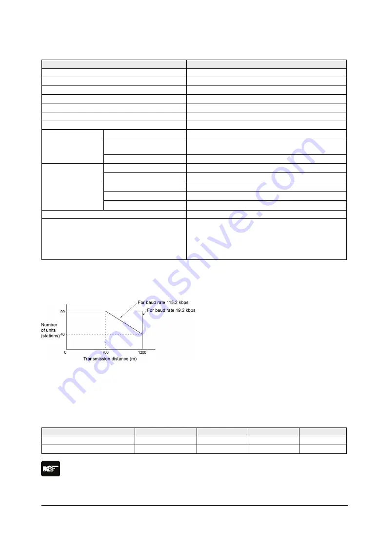
Transmission distance
Max. 1200 m
Note1) 2)
Baud rate
19200, 115200 bps
Note2) 3))
Communication method
Two-wire, half-duplex transmission
Synchronous method
Start stop synchronous system
Transmission line
Shielded twisted-pair cable or VCTF
Transmission
code
Computer link
ASCII
General-purpose serial
communication
ASCII, Binary
MODBUS RTU
Binary
Communication
format (to be set
by system
register)
Note4)
Data length
7 bits/8bits
Parity
7 bits/8bits
Stop bit
None/Even/Odd
Start code
STX/No STX
End code
CR/CR+LF/None/ETX
No. of connected units
Note2) 5)
Transmits from bit 0 character by character.
Communication function
Computer link (Master/Slave)
Modem initialization
General-purpose communication
MODBUS RTU (Master/Slave)
PC(PLC) link
Note1) When connecting a commercially available device that has an RS485 interface, please confirm
operation using the actual device. In some cases, the number of units, transmission distance, and baud
rate vary depending on the connected device.
Note2) The values for the transmission distance, baud rate and number of units should be within the
values noted in the graph below.
Note3) The settings of the baud rate switches on the side of the unit and the system register No. 415
should be the same. Only 19200 bps can be specified when the C-NET adapter is connected with the
RS485 interface.
Note4) The start code and end code can be used only in the general-purpose serial communication
mode.
Note5) Unit numbers should be registered by the system register.
Factory default
Port type
Baud rate
Data length
Parity
Stop bit
Tool port
9600 bit/s
8 bits
Odd
1 bit
COM port (RS485 port)
115200 bit/s
8 bits
Odd
1 bit
Note:
If the potential difference between the power supplies of RS485 devices exceeds 4 V, the unit may not
communicate as it is the non-isolated type. The large potential difference leads to the damage to the
devices.
Summary of Contents for FP0R Series
Page 1: ......
Page 6: ...iv ...
Page 14: ...xii ...
Page 15: ...Chapter 1 Functions and Restrictions of the Unit ...
Page 24: ...1 10 ...
Page 25: ...Chapter 2 Specifications and Functions of Control Unit ...
Page 38: ...2 14 ...
Page 39: ...Chapter 3 Expansion ...
Page 45: ...3 7 3 4 Terminal layout diagram Model No Terminal layout diagrams E8RS E8RM E16RS E16RM E8YRS ...
Page 48: ...3 10 ...
Page 49: ...Chapter 4 I O Allocation ...
Page 53: ...Chapter 5 Installation and Wiring ...
Page 73: ...Chapter 6 Preparation of USB Port ...
Page 77: ...6 5 5 Click Finish on the following screen to be displayed ...
Page 79: ...6 7 4 Double click on FP0R 5 Click Update Driver ...
Page 84: ...6 12 ...
Page 85: ...Chapter 7 Communication ...
Page 139: ...7 55 Sample program For Type II Use a program as below to directly specify a MODBUS address ...
Page 141: ...Chapter 8 High speed Counter Pulse Output and PWM Output Functions ...
Page 142: ...8 2 ...
Page 199: ...Chapter 9 Security Functions ...
Page 211: ...Chapter 10 Other Functions ...
Page 217: ...Chapter 11 Self Diagnostic and Troubleshooting ...
Page 227: ...Chapter 12 Precautions During Programming ...
Page 242: ...12 16 ...
Page 243: ...Chapter 13 Specifications ...
Page 254: ...13 12 ...
Page 255: ...Chapter 14 Dimensions and Others ...
Page 262: ...14 8 ...
Page 263: ...Chapter 15 Appendix ...
Page 344: ...15 82 15 7 ASCII Codes ...
Page 346: ......
Page 347: ......
Page 348: ......


