9-8
9.2 Upload Protection
9.2.1 Upload Protection
Overview of program upload protection function
-
This function is to prohibit reading programs and system registers by setting to disable program
uploading.
-
If the upload protection is set, note that the ladder programs and system registers will be disabled to be
uploaded after that. Transferring programs to the FP memory loader will be also unperformable.
-
The setting can be cancelled using the programming tool, however, all ladder programs, system
registers and password information will be deleted when the setting is cancelled.
-
Editing the files that are controlled with a PC can be carried out online using the programming tool.
However, the programs will be broken if the programs are not absolutely matched. When using this
function, store ladder programs as files without fail.
Interaction with the password protect function
-
The password setting can be specified simultaneously for the PLC in which this function is set.
-
This function can be also set in a password-protected PLC.
Note:
When performing "Release the upload-protection by compulsion"
-
All programs and security information will be deleted when the upload protection setting is cancelled.
We cannot restore the deleted programs even if you ask us. We cannot read the data of the PLC in
which the program upload protection has been set. Keeping your programs is your responsibility.
9.2.2 Setting Method
Use the programming tool to set the upload protection on the control unit.
Upload protection setting with FPWIN GR
1. Select "Online" > "Online Edit Mode" in the menu bar, and press the CTRL and F2 keys. The screen is
switched to "Online Monitor".
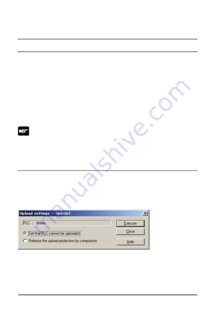
2. Select "Tool" > "Upload settings" in the menu bar.
The "Upload settings" dialog box is displayed.
3. Select "Set the PLC cannot be uploaded.", and press the "Execute" button.
Force Cancel with FPWIN GR
Select "Release the upload-protection by compulsion" in the "Upload settings" dialog box, and press the
"Execute" button.
Summary of Contents for FP0R Series
Page 1: ......
Page 6: ...iv ...
Page 14: ...xii ...
Page 15: ...Chapter 1 Functions and Restrictions of the Unit ...
Page 24: ...1 10 ...
Page 25: ...Chapter 2 Specifications and Functions of Control Unit ...
Page 38: ...2 14 ...
Page 39: ...Chapter 3 Expansion ...
Page 45: ...3 7 3 4 Terminal layout diagram Model No Terminal layout diagrams E8RS E8RM E16RS E16RM E8YRS ...
Page 48: ...3 10 ...
Page 49: ...Chapter 4 I O Allocation ...
Page 53: ...Chapter 5 Installation and Wiring ...
Page 73: ...Chapter 6 Preparation of USB Port ...
Page 77: ...6 5 5 Click Finish on the following screen to be displayed ...
Page 79: ...6 7 4 Double click on FP0R 5 Click Update Driver ...
Page 84: ...6 12 ...
Page 85: ...Chapter 7 Communication ...
Page 139: ...7 55 Sample program For Type II Use a program as below to directly specify a MODBUS address ...
Page 141: ...Chapter 8 High speed Counter Pulse Output and PWM Output Functions ...
Page 142: ...8 2 ...
Page 199: ...Chapter 9 Security Functions ...
Page 211: ...Chapter 10 Other Functions ...
Page 217: ...Chapter 11 Self Diagnostic and Troubleshooting ...
Page 227: ...Chapter 12 Precautions During Programming ...
Page 242: ...12 16 ...
Page 243: ...Chapter 13 Specifications ...
Page 254: ...13 12 ...
Page 255: ...Chapter 14 Dimensions and Others ...
Page 262: ...14 8 ...
Page 263: ...Chapter 15 Appendix ...
Page 344: ...15 82 15 7 ASCII Codes ...
Page 346: ......
Page 347: ......
Page 348: ......


