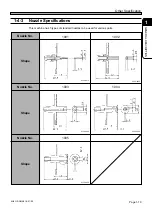
Page 1-12
1-2
Mounting Mechanism
This section describes the mounting mechanism in due order.
Mobile Parts
1
The board transported in
from the previous process
is set in the board holder
on the stage A.
2
Two head units (four heads in
all) mount chips precisely.
Alternate mounting
While one head unit
recognizes and mounts
chips, the other head unit
picks up and recognizes
chips.
Transporting
board in
1
A board is transported in from
the previous process.
2
The board is clamped and
recognized.
Mounting chips
444C-106E
H2
From previous process
To next process
Rear side
Front side
H1
3
4
5
5
2
3
4
1
3
Picking up chips
4H4C-016P
4H4C-006E
Tray Feeder Supply Area
4H4C-006P
5
Mounting the chips
4H4C-017P
4
Recognizing the chips in a row
4H4C-015P
4H4C-014P
4
3
5
5
4
3
4H4C-E-OMA01-A01-01
6
Tape Feeder Supply Area
: Head
: Line Camera
Summary of Contents for CM301
Page 2: ......
Page 6: ...Page 4 4H4C E OMA00 B01 00 MEMO ...
Page 19: ...Page 17 SAFETY PRECAUTIONS Be sure to observe 4H4C E OMA00 A03 02 WARNING ...
Page 64: ...Page 1 20 MEMO 4H4C E OMA01 A01 01 ...
Page 78: ...Page 2 14 MEMO 4H4C E OMA02 A01 01 ...


