10400455-002
©2008-14 Overland Storage, Inc.
17
SnapScale/RAINcloudOS 4.1 Administrator’s Guide
1 - Overview
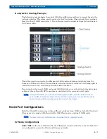
Node/Switch Cabling Example
The following example shows three dual 10GbE card X2 nodes and how to connect them to the
network switches. The cables used to connect to the Client side of the network (blue) originate
from the Client 10GbE card in slot 1. Two cables are used to connect both ports of each node to
the Client switch.
The cables used to connect to the Storage side of the network (orange) originate from the
Storage 10GbE card in slot 2. For each node, one cable is used to connect a one Storage port of
each note to one of the two Storage switches used for failover.
For connections between 10GbE cards and 10GbE switches, use either direct-attached copper
cables or fibre cables with SFP+ modules pre-installed in the card and switch ports.
NOTE: If using fibre cables, you must use Overland-approved SFP+ modules. With the cluster
powered OFF, insert the modules into the card and switch ports. Connect the fibre cable
between the two SFP+ modules and restore power to the cluster.
Node Port Configurations
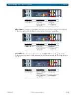
Both the X2 and X4 nodes come in three different configurations: 1GbE ports (both Client and
Storage ports), a single 10GbE card (with 1GbE Client ports), and dual 10GbE cards.
NOTE: If desired, optional 10GbE cards can be added later to upgrade the node.
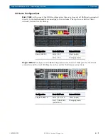
X2 Node Configurations
Basic 1GbE.
At the rear of the X2 node, the 1GbE ports connected directly to the motherboard
are configured to access the Client and Storage networks.

