
SECTION 4 - BOOM & PLATFORM
3121827
– JLG Lift –
4-37
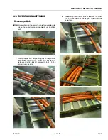
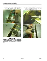
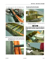
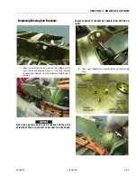
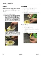
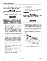
Replacing Moving End Brackets
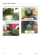
1.
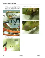
Remove existing pins and center rivet. Remove the
rivet the same way as shown in the link removal
instructions. Repeat on other bracket if replacing it
as well.
MOVE THE CABLES/HOSES OUT OF THE WAY DURING THE
GRINDING PROCESS TO PROTECT THEM. KEEP THE HOSES AND
CABLES COVERED TO PREVENT ANY DEBRIS FROM GETTING ON
THEM.
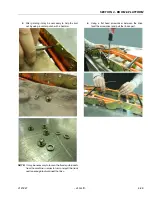
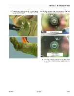
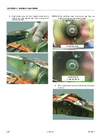
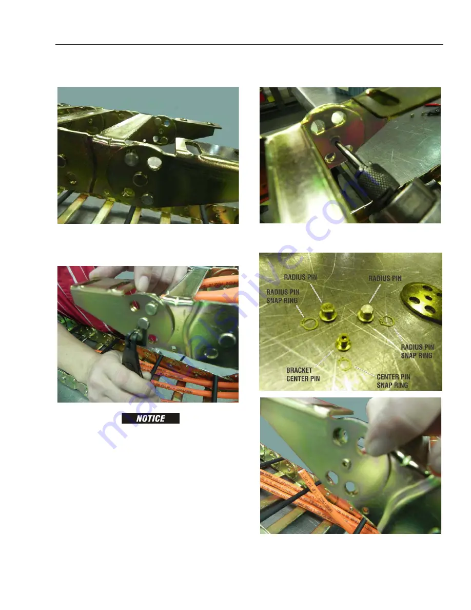
2.
Take new bracket and install center pin with snap
ring.
Summary of Contents for JLG E400AJP
Page 2: ......
Page 32: ...SECTION 1 SPECIFICATIONS 1 18 JLG Lift 3121827 NOTES...
Page 42: ...SECTION 2 GENERAL 2 10 JLG Lift 3121827 NOTES...
Page 54: ...SECTION 3 CHASSIS TURNTABLE 3 12 JLG Lift 3121827 Figure 3 3 Speed Sensor Orientation...
Page 60: ...SECTION 3 CHASSIS TURNTABLE 3 18 JLG Lift 3121827 Figure 3 7 Steering Components and Spindles...
Page 62: ...SECTION 3 CHASSIS TURNTABLE 3 20 JLG Lift 3121827 Figure 3 9 Tilt Sensor Location...
Page 86: ...SECTION 3 CHASSIS TURNTABLE 3 44 JLG Lift 3121827 Figure 3 16 Swing Components...
Page 88: ...SECTION 3 CHASSIS TURNTABLE 3 46 JLG Lift 3121827 Figure 3 18 Battery Cable Connections...
Page 90: ...SECTION 3 CHASSIS TURNTABLE 3 48 JLG Lift 3121827 Figure 3 20 On Board Generator...
Page 97: ...SECTION 3 CHASSIS TURNTABLE 3121827 JLG Lift 3 55 Figure 3 22 Generator Components...
Page 116: ...SECTION 3 CHASSIS TURNTABLE 3 74 JLG Lift 3121827 NOTES...
Page 127: ...SECTION 4 BOOM PLATFORM 3121827 JLG Lift 4 11 Figure 4 10 Boom Limit Switches...
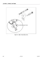
Page 140: ...SECTION 4 BOOM PLATFORM 4 24 JLG Lift 3121827 Figure 4 13 Rotator Counterbalance Valve...
Page 178: ...SECTION 5 HYDRAULICS 5 24 JLG Lift 3121827 Figure 5 26 HydraForce Cartridge Torque Value Chart...
Page 214: ...SECTION 6 JLG CONTROL SYSTEM 6 34 JLG Lift 3121827 NOTES...
Page 257: ......


