


SECTION 3 - CHASSIS & TURNTABLE
3121827
– JLG Lift –
3-17
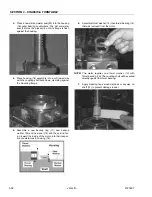
18.
While watching the analyzer display, select drive for-
ward. Be ready to remove your foot from the foot
switch if the machine lunges forward.
19.
The analyzer display should read the following if the
left speed sensor is adjusted properly: “SPEED 20%
FWD”.
20.
If the left speed sensor is adjusted improperly, the
analyzer will display “SPEED 20% REV”, and the
machine will lunge forward.
21.
Adjust the left speed sensor using the preceding
Adjustment Procedure
until the analyzer displays
“SPEED 20% FWD” when forward is selected in the
platform. The percentage displayed is not critical,
just the direction.
22.
After obtaining the display in step 10, operate the
machine in both the forward and reverse directions.
The machine should be controllable in both direc-
tions and will only drive at a maximum of creep
speed. The display on the analyzer should match
the direction selected.
23.
Plug in the right sensor to the power module.
24.
Test the machine. The machine should now have
maximum drive speed available in both directions
and should be controllable in both directions. The
analyzer display should match the direction
selected.
Summary of Contents for JLG E400AJP
Page 2: ......
Page 32: ...SECTION 1 SPECIFICATIONS 1 18 JLG Lift 3121827 NOTES...
Page 42: ...SECTION 2 GENERAL 2 10 JLG Lift 3121827 NOTES...
Page 54: ...SECTION 3 CHASSIS TURNTABLE 3 12 JLG Lift 3121827 Figure 3 3 Speed Sensor Orientation...
Page 60: ...SECTION 3 CHASSIS TURNTABLE 3 18 JLG Lift 3121827 Figure 3 7 Steering Components and Spindles...
Page 62: ...SECTION 3 CHASSIS TURNTABLE 3 20 JLG Lift 3121827 Figure 3 9 Tilt Sensor Location...
Page 86: ...SECTION 3 CHASSIS TURNTABLE 3 44 JLG Lift 3121827 Figure 3 16 Swing Components...
Page 88: ...SECTION 3 CHASSIS TURNTABLE 3 46 JLG Lift 3121827 Figure 3 18 Battery Cable Connections...
Page 90: ...SECTION 3 CHASSIS TURNTABLE 3 48 JLG Lift 3121827 Figure 3 20 On Board Generator...
Page 97: ...SECTION 3 CHASSIS TURNTABLE 3121827 JLG Lift 3 55 Figure 3 22 Generator Components...
Page 116: ...SECTION 3 CHASSIS TURNTABLE 3 74 JLG Lift 3121827 NOTES...
Page 127: ...SECTION 4 BOOM PLATFORM 3121827 JLG Lift 4 11 Figure 4 10 Boom Limit Switches...
Page 140: ...SECTION 4 BOOM PLATFORM 4 24 JLG Lift 3121827 Figure 4 13 Rotator Counterbalance Valve...
Page 178: ...SECTION 5 HYDRAULICS 5 24 JLG Lift 3121827 Figure 5 26 HydraForce Cartridge Torque Value Chart...
Page 214: ...SECTION 6 JLG CONTROL SYSTEM 6 34 JLG Lift 3121827 NOTES...
Page 257: ......


