SECTION 3 - CHASSIS & TURNTABLE
3121827
– JLG Lift –
3-65
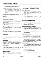
Fuel Pump
The fuel pump runs in parallel with the fuel solenoid hold
coil which is run by the fuel control relay.
The pump runs whenever the engine runs, and keeps the
fuel filter filled. Excess fuel flows through the return line
back to the fuel tank.
The fuel pump is located on the right side of the engine.
Fuel Solenoid
The fuel solenoid actuates the run/stop lever of the
engine. This solenoid has a pull coil energized by the start
control relay and a hold coil energized by the fuel control
relay.
The fuel solenoid is located on the right side of the engine.
Engine Low Oil Pressure Switch
The engine is equipped with a low oil pressure switch.
This switch is closed when the oil pressure is below 7psi.
It is mounted on the side cover.
Engine Oil Temperature Sensor
The engine oil temperature sensor is used to sense the
temperature of the oil in the sump of the engine.
This sensor provides an analog signal to the engine/gen-
erator controller. The primary use of this signal is for high
engine temperature shutdown 248°F (120°C) for the
Summary of Contents for JLG E400AJP
Page 2: ......
Page 32: ...SECTION 1 SPECIFICATIONS 1 18 JLG Lift 3121827 NOTES...
Page 42: ...SECTION 2 GENERAL 2 10 JLG Lift 3121827 NOTES...
Page 54: ...SECTION 3 CHASSIS TURNTABLE 3 12 JLG Lift 3121827 Figure 3 3 Speed Sensor Orientation...
Page 60: ...SECTION 3 CHASSIS TURNTABLE 3 18 JLG Lift 3121827 Figure 3 7 Steering Components and Spindles...
Page 62: ...SECTION 3 CHASSIS TURNTABLE 3 20 JLG Lift 3121827 Figure 3 9 Tilt Sensor Location...
Page 86: ...SECTION 3 CHASSIS TURNTABLE 3 44 JLG Lift 3121827 Figure 3 16 Swing Components...
Page 88: ...SECTION 3 CHASSIS TURNTABLE 3 46 JLG Lift 3121827 Figure 3 18 Battery Cable Connections...
Page 90: ...SECTION 3 CHASSIS TURNTABLE 3 48 JLG Lift 3121827 Figure 3 20 On Board Generator...
Page 97: ...SECTION 3 CHASSIS TURNTABLE 3121827 JLG Lift 3 55 Figure 3 22 Generator Components...
Page 116: ...SECTION 3 CHASSIS TURNTABLE 3 74 JLG Lift 3121827 NOTES...
Page 127: ...SECTION 4 BOOM PLATFORM 3121827 JLG Lift 4 11 Figure 4 10 Boom Limit Switches...
Page 140: ...SECTION 4 BOOM PLATFORM 4 24 JLG Lift 3121827 Figure 4 13 Rotator Counterbalance Valve...
Page 178: ...SECTION 5 HYDRAULICS 5 24 JLG Lift 3121827 Figure 5 26 HydraForce Cartridge Torque Value Chart...
Page 214: ...SECTION 6 JLG CONTROL SYSTEM 6 34 JLG Lift 3121827 NOTES...
Page 257: ......


