SECTION 3 - CHASSIS & TURNTABLE
3121827
– JLG Lift –
3-31
SINCE THEY ARE FLAMMABLE, BE EXTREMELY CAREFUL WHEN
USING ANY SOLVENT. EVEN A SMALL EXPLOSION OR FIRE
COULD CAUSE INJURY OR DEATH.
WEAR EYE PROTECTION AND BE SURE TO COMPLY WITH OSHA
OR OTHER MAXIMUM AIR PRESSURE REQUIREMENTS.
1.
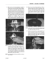
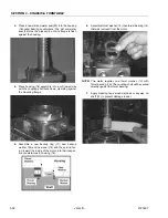
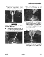
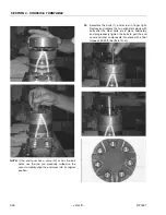
If the housing (18) bearing components were
removed for replacement, thoroughly coat and pack
a new outer bearing/bushing (19) with clean corro-
sion resistant grease recommended in the material
section. Press the new bearing/bushing into the
counterbore at the mounting flange end of the hous-
ing, using the appropriate sized bearing mandrel as
described which will control the bearing/ bushing
depth.
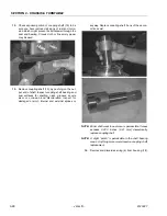
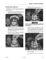
The housing requires the use of bearing mandrel to
press bearing/ bushing (19) into the housing to a
required depth of 0.151/0.161 inches (3.84/4.09
mm) from the end of the bearing counterbore.
NOTE:
Bearing mandrel must be pressed against the let-
tered end of bearing shell. Take care that the hous-
ing bore is square with the press base and the
bearing/ bushing is not cocked when pressing a
bearing/bushing into the housing.
IF A BEARING MANDREL IS NOT AVAILABLE AND ALTERNATE
METHODS ARE USED TO PRESS IN BEARING/BUSHING (13) AND
(19) THE BEARING/BUSHING DEPTHS SPECIFIED MUST BE
ACHIEVED TO INSURE ADEQUATE BEARING SUPPORT AND COR-
RECT RELATIONSHIP TO ADJACENT COMPONENTS WHEN
ASSEMBLED.
BECAUSE THE BEARING/BUSHINGS (13) AND (19) HAVE A
PRESS FIT INTO THE HOUSING THEY MUST BE DISCARDED
WHEN REMOVED. THEY MUST NOT BE REUSED.
2.
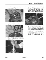
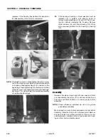
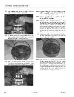
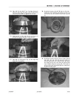
The inner housing bearing/bushing (13) can now be
pressed into its counter-bore in housing (18) flush to
0.03 inch (0.76 mm) below the housing wear plate
contact face. Use the opposite end of the bearing
mandrel that was used to press in the outer bearing/
bushing (19).
Summary of Contents for JLG E400AJP
Page 2: ......
Page 32: ...SECTION 1 SPECIFICATIONS 1 18 JLG Lift 3121827 NOTES...
Page 42: ...SECTION 2 GENERAL 2 10 JLG Lift 3121827 NOTES...
Page 54: ...SECTION 3 CHASSIS TURNTABLE 3 12 JLG Lift 3121827 Figure 3 3 Speed Sensor Orientation...
Page 60: ...SECTION 3 CHASSIS TURNTABLE 3 18 JLG Lift 3121827 Figure 3 7 Steering Components and Spindles...
Page 62: ...SECTION 3 CHASSIS TURNTABLE 3 20 JLG Lift 3121827 Figure 3 9 Tilt Sensor Location...
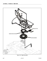
Page 86: ...SECTION 3 CHASSIS TURNTABLE 3 44 JLG Lift 3121827 Figure 3 16 Swing Components...
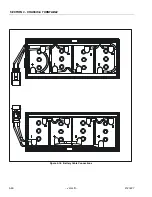
Page 88: ...SECTION 3 CHASSIS TURNTABLE 3 46 JLG Lift 3121827 Figure 3 18 Battery Cable Connections...
Page 90: ...SECTION 3 CHASSIS TURNTABLE 3 48 JLG Lift 3121827 Figure 3 20 On Board Generator...
Page 97: ...SECTION 3 CHASSIS TURNTABLE 3121827 JLG Lift 3 55 Figure 3 22 Generator Components...
Page 116: ...SECTION 3 CHASSIS TURNTABLE 3 74 JLG Lift 3121827 NOTES...
Page 127: ...SECTION 4 BOOM PLATFORM 3121827 JLG Lift 4 11 Figure 4 10 Boom Limit Switches...
Page 140: ...SECTION 4 BOOM PLATFORM 4 24 JLG Lift 3121827 Figure 4 13 Rotator Counterbalance Valve...
Page 178: ...SECTION 5 HYDRAULICS 5 24 JLG Lift 3121827 Figure 5 26 HydraForce Cartridge Torque Value Chart...
Page 214: ...SECTION 6 JLG CONTROL SYSTEM 6 34 JLG Lift 3121827 NOTES...
Page 257: ......


