


SECTION 6 - JLG CONTROL SYSTEM
3121827
– JLG Lift –
6-27
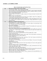
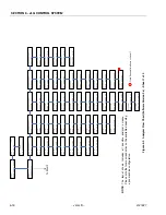
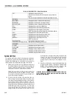
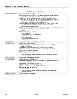
TEST ALL INPUTS?
Prompts whether to check every operator input. If ESC is pressed, the system test ends.
If ENTER is pressed, each operator input is prompted for in turn.
In platform mode, operator inputs are tested in the order: UL U, UL D, SWING L, SWING R, LEVEL U, LEVEL D,
PUMP POT, CREEP, ROTATE L, ROTATE R, LL U, LL D, JIB U, JIB D, TELE I, TELE O, DRIVE FWD,
DRIVE REV, STEER L, STEER R, POSITRAC
In ground mode, operator inputs are tested in the order: ROTATE L, ROTATE R. LEVEL U. LEVEL D, JIB U. JIB D,
TELE I, TELE O. UL U. IJL D, LL U. LL D, SWING L, SWING R
NOTE: the jib switches are not tested if JIB = NO.
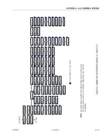
Prompts displayed during the operator input test include:
CLOSE switch name
The named switch should be closed.
OPEN switch name
The named switch should be opened.
joystick name direction TO MAX
The named joystick should be pushed to its full extent in the named direction.
joystick name direction TO MIN
The named joystick should be returned to neutral from the named direction.
PUMP POT TO MAX
The pump pot should be turned to maximum.
PUMP POT TO MIN
The pump pot should be turned to minimum.
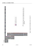
MULTIPLE CLOSURE
More than one operator input is closed; if only one has been operated, there could be a short between two inputs.
TESTS COMPLETE
Indicates that the system test is complete. Any problems reported should have been noted and should now be rectified.
Press ESC to return to the RUN SYSTEM TEST Analyzer menu.
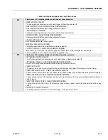
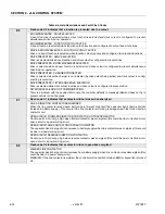
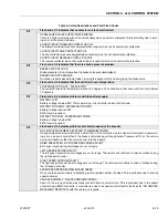
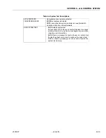
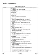
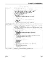
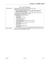
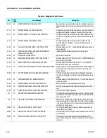
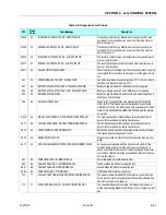
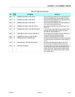
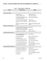
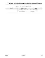
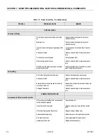
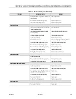
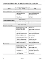
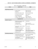
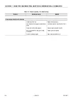
Table 6-7. System Test Messages
Summary of Contents for JLG E400AJP
Page 2: ......
Page 32: ...SECTION 1 SPECIFICATIONS 1 18 JLG Lift 3121827 NOTES...
Page 42: ...SECTION 2 GENERAL 2 10 JLG Lift 3121827 NOTES...
Page 54: ...SECTION 3 CHASSIS TURNTABLE 3 12 JLG Lift 3121827 Figure 3 3 Speed Sensor Orientation...
Page 60: ...SECTION 3 CHASSIS TURNTABLE 3 18 JLG Lift 3121827 Figure 3 7 Steering Components and Spindles...
Page 62: ...SECTION 3 CHASSIS TURNTABLE 3 20 JLG Lift 3121827 Figure 3 9 Tilt Sensor Location...
Page 86: ...SECTION 3 CHASSIS TURNTABLE 3 44 JLG Lift 3121827 Figure 3 16 Swing Components...
Page 88: ...SECTION 3 CHASSIS TURNTABLE 3 46 JLG Lift 3121827 Figure 3 18 Battery Cable Connections...
Page 90: ...SECTION 3 CHASSIS TURNTABLE 3 48 JLG Lift 3121827 Figure 3 20 On Board Generator...
Page 97: ...SECTION 3 CHASSIS TURNTABLE 3121827 JLG Lift 3 55 Figure 3 22 Generator Components...
Page 116: ...SECTION 3 CHASSIS TURNTABLE 3 74 JLG Lift 3121827 NOTES...
Page 127: ...SECTION 4 BOOM PLATFORM 3121827 JLG Lift 4 11 Figure 4 10 Boom Limit Switches...
Page 140: ...SECTION 4 BOOM PLATFORM 4 24 JLG Lift 3121827 Figure 4 13 Rotator Counterbalance Valve...
Page 178: ...SECTION 5 HYDRAULICS 5 24 JLG Lift 3121827 Figure 5 26 HydraForce Cartridge Torque Value Chart...
Page 214: ...SECTION 6 JLG CONTROL SYSTEM 6 34 JLG Lift 3121827 NOTES...
Page 257: ......


