SECTION 4 - BOOM & PLATFORM
3121827
– JLG Lift –
4-19
Inspection
1.
Clean all parts in a solvent tank and dry with com-
pressed air prior to inspecting. Carefully inspect all
critical areas for any surface finish abnormalities:
Seal grooves, bearing grooves, thrust surfaces, rod
surface, housing bore and gear teeth.
2.
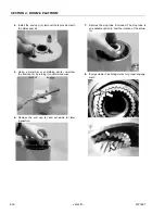
Inspect the thrust washers (304) for rough or worn
edges and surfaces. Measure it’s thickness to make
sure it is within specifications (Not less than 0.092”
or 2.34 mm).
3.
Inspect the wear guide condition and measure thick-
ness (not less than 0.123” or 3.12 mm).
Assembly
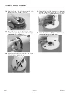
1.
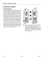
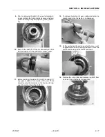
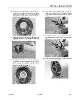
Gather all the components and tools into one loca-
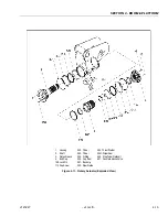
tion prior to re-assembly. Use the cut away drawing
to reference the seal orientations.
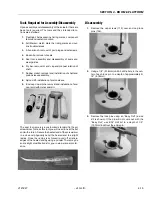
2.
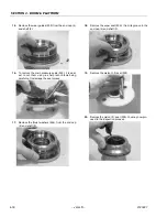
Install the thrust washer (304) onto shaft (2) and end
cap (4).
3.
Install the wiper seal (304.1/green O-ring) into it’s
groove on the shaft (2) and end cap (4) around the
outside edge of the thrust washer (304).
Summary of Contents for JLG E400AJP
Page 2: ......
Page 32: ...SECTION 1 SPECIFICATIONS 1 18 JLG Lift 3121827 NOTES...
Page 42: ...SECTION 2 GENERAL 2 10 JLG Lift 3121827 NOTES...
Page 54: ...SECTION 3 CHASSIS TURNTABLE 3 12 JLG Lift 3121827 Figure 3 3 Speed Sensor Orientation...
Page 60: ...SECTION 3 CHASSIS TURNTABLE 3 18 JLG Lift 3121827 Figure 3 7 Steering Components and Spindles...
Page 62: ...SECTION 3 CHASSIS TURNTABLE 3 20 JLG Lift 3121827 Figure 3 9 Tilt Sensor Location...
Page 86: ...SECTION 3 CHASSIS TURNTABLE 3 44 JLG Lift 3121827 Figure 3 16 Swing Components...
Page 88: ...SECTION 3 CHASSIS TURNTABLE 3 46 JLG Lift 3121827 Figure 3 18 Battery Cable Connections...
Page 90: ...SECTION 3 CHASSIS TURNTABLE 3 48 JLG Lift 3121827 Figure 3 20 On Board Generator...
Page 97: ...SECTION 3 CHASSIS TURNTABLE 3121827 JLG Lift 3 55 Figure 3 22 Generator Components...
Page 116: ...SECTION 3 CHASSIS TURNTABLE 3 74 JLG Lift 3121827 NOTES...
Page 127: ...SECTION 4 BOOM PLATFORM 3121827 JLG Lift 4 11 Figure 4 10 Boom Limit Switches...
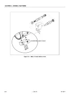
Page 140: ...SECTION 4 BOOM PLATFORM 4 24 JLG Lift 3121827 Figure 4 13 Rotator Counterbalance Valve...
Page 178: ...SECTION 5 HYDRAULICS 5 24 JLG Lift 3121827 Figure 5 26 HydraForce Cartridge Torque Value Chart...
Page 214: ...SECTION 6 JLG CONTROL SYSTEM 6 34 JLG Lift 3121827 NOTES...
Page 257: ......


