SECTION 6 - JLG CONTROL SYSTEM
6-30
– JLG Lift –
3121827
2514
25
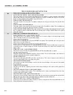
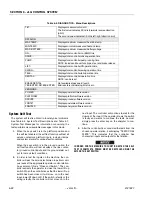
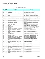
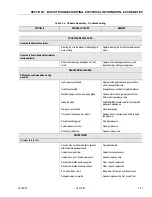
BOOM PREVENTED - DRIVE SELECTED
Boom functions are not possible while the vehicle is being driven
AND is configured to not allow simultaneous drive & boom opera-
tion.
2516
25
DRIVE PREVENTED - ABOVE ELEVATION
Driving is not possible while Boom functions are selected AND is
configured to not allow simultaneous drive & boom operation.
2517
25
DRIVE PREVENTED - TILTED & ABOVE ELEVATION
Driving is not possible while the vehicle is tilted and above eleva-
tion AND is configured to prevent drive while tilted and above ele-
vation.
2518
25
DRIVE PREVENTED - BOOM SELECTED
Driving is not possible while the vehicle boom functions are
selected AND is configured to not allow simultaneous drive &
boom operation.
2536
25
ALL FUNCTIONS PREVENTED - FUNCTION CUTOUT
Machine Setup’s set for "1 =CHARGER & BOOM" and machine is
above elevation
2542
25
FUNCTION PREVENTED - BRAKES ELECTRONICALL Y
RELEASED FOR TOWING
Indicates Manual Brake release active in Ground mode
2548
25
SYSTEM TEST MODE ACTIVE
System test mode active
2549
25
DRIVE & BOOM PREVENTED - SOFT TOUCH ACTIVE
Machine Setup’s SOFT TOUCH is set for "2=BOOM & DRIVE" and
Soft touch switch is OPEN
2550
25
BOOM PREVENTED - FUNCTION CUTOUT ACTIVE
Machine Setup’s DRIVE CUTOUT is set for "1 =CHARGER &
BOOM" and machine is above elevation
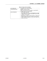
2551
25
TELESCOPE OUT PREVENTED - TIL TED & ABOVE ELEVATION
Telescope OUT is not possible while the vehicle is tilted and above
elevation AND is configured to prevent drive while tilted and
above elevation.
2552
25
LIFT UP PREVENTED - TILTED & ABOVE ELEVATION
Lift UP is not possible while the vehicle is tilted and above eleva-
tion AND is configured to prevent drive while tilted and above ele-
vation.
2553
25
LEVELING PREVENTED - ABOVE ELEVATION
Machine Setup’s LEVEL inhibit is set for "1 =ELEV" and machine
is above elevation
2554
25
DRIVE PREVENTED - SPEED SENSORS FAULTY
Both Speed sensor input voltages are out of range
2555
25
FUNCTION PREVENTED - SELECTED BEFORE FSW
Function switch was selected before and during foot switch clo-
sure
2556
25
FUNCTION PREVENTED - SELECTED BEFORE EMS
Function was CLOSED at power up
321
32
LINE CONTACTOR WELDED OR MISWIRED
The capacitor bank charge did not decrease from battery supply
when line contactor was de-energized (this could be caused due
to a power wiring error)
325
32
LINE & DIRECTION CONTACTORS MISWIRED
When the line contactor was closed, traction point A went HIGH
(and the capacitor bank charge did not increase to battery supply)
- this occurs if the line contactor coil wiring is swapped with that
for a direction contactor coil
33300
33
LINE CONTACTOR COIL - OPEN CIRCUIT
The capacitor bank did not increase to battery supply when the
line contactor was CLOSED
33301
33
LINE CONT ACTOR COIL - SHORT TO GROUND
Line contactor was not energized when required, due to over cur-
rent protection
33361
33
DIRECTION CONTACTOR COIL - OPEN CIRCUIT
Traction point A is collapsing when the traction MOSFETs are
pulsed. This maybe due to an open circuit traction motor or power
wiring error
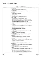
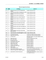
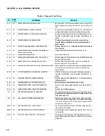
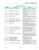
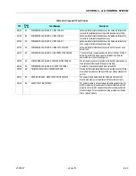
Table 6-8. Diagnostic Fault Codes
DTC
Flash
Code
Fault Message
Description
Summary of Contents for JLG E400AJP
Page 2: ......
Page 32: ...SECTION 1 SPECIFICATIONS 1 18 JLG Lift 3121827 NOTES...
Page 42: ...SECTION 2 GENERAL 2 10 JLG Lift 3121827 NOTES...
Page 54: ...SECTION 3 CHASSIS TURNTABLE 3 12 JLG Lift 3121827 Figure 3 3 Speed Sensor Orientation...
Page 60: ...SECTION 3 CHASSIS TURNTABLE 3 18 JLG Lift 3121827 Figure 3 7 Steering Components and Spindles...
Page 62: ...SECTION 3 CHASSIS TURNTABLE 3 20 JLG Lift 3121827 Figure 3 9 Tilt Sensor Location...
Page 86: ...SECTION 3 CHASSIS TURNTABLE 3 44 JLG Lift 3121827 Figure 3 16 Swing Components...
Page 88: ...SECTION 3 CHASSIS TURNTABLE 3 46 JLG Lift 3121827 Figure 3 18 Battery Cable Connections...
Page 90: ...SECTION 3 CHASSIS TURNTABLE 3 48 JLG Lift 3121827 Figure 3 20 On Board Generator...
Page 97: ...SECTION 3 CHASSIS TURNTABLE 3121827 JLG Lift 3 55 Figure 3 22 Generator Components...
Page 116: ...SECTION 3 CHASSIS TURNTABLE 3 74 JLG Lift 3121827 NOTES...
Page 127: ...SECTION 4 BOOM PLATFORM 3121827 JLG Lift 4 11 Figure 4 10 Boom Limit Switches...
Page 140: ...SECTION 4 BOOM PLATFORM 4 24 JLG Lift 3121827 Figure 4 13 Rotator Counterbalance Valve...
Page 178: ...SECTION 5 HYDRAULICS 5 24 JLG Lift 3121827 Figure 5 26 HydraForce Cartridge Torque Value Chart...
Page 214: ...SECTION 6 JLG CONTROL SYSTEM 6 34 JLG Lift 3121827 NOTES...
Page 257: ......

