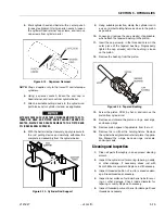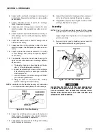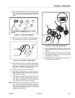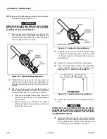
SECTION 6 - JLG CONTROL SYSTEM
3121827
– JLG Lift –
6-3
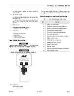
Using the Analyzer
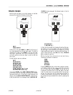
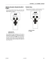
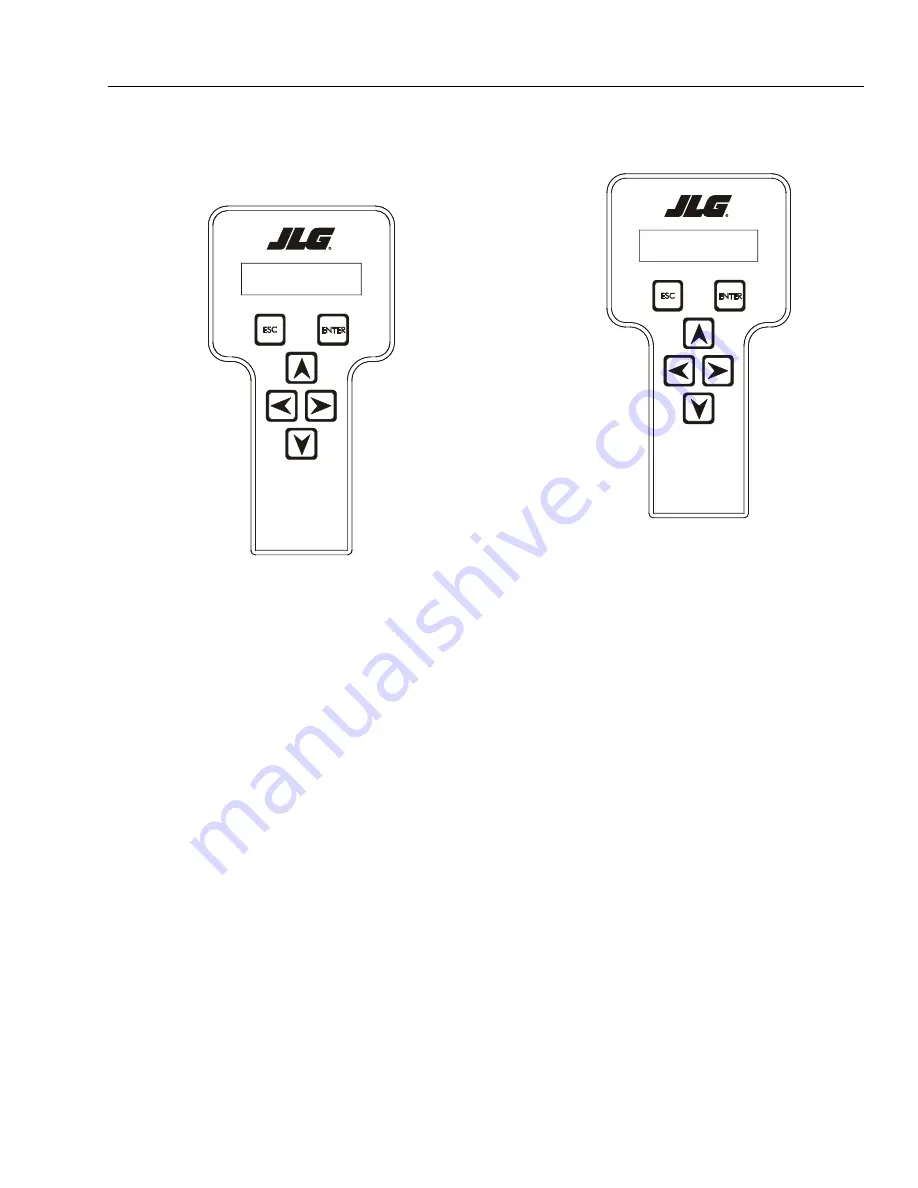
With the machine power on and the analyzer connected
properly, the analyzer will display the following:
HELP:
PRESS ENTER
At this point, using the
RIGHT
and
LEFT
arrow keys, you
can move between the top level menu items. To select a
displayed menu item, press
ENTER
. To cancel a selected
menu item, press ESC.; then you will be able to scroll
using the right and left arrow keys to select a different
menu item.
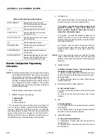
The top level menus are as follows:
HELP
DIAGNOSTICS
ACTIVATE TEST
ACCESS LEVEL
PERSONALITIES
MACHINE SETUP
LEVEL VEHICLE (level 1 only)
CALIBRATIONS (view only)
If you press
ENTER
, at the
HELP: PRESS ENTER
display,
and a fault is present, the analyzer display will scroll the
fault across the screen. If there was no fault detected, the
display will read:
HELP: EVERYTHING OK.
If powered up
at the ground station, the display will read:
GROUND OK.
If
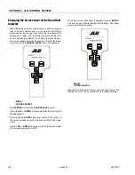
ENTER
is pressed again, the display moves to the fol-
lowing display:
LOGGED HELP
1: STARTUP (2/1
)
At this point, the analyzer will display the last fault the sys-
tem has seen, if any are present. You may scroll through
the fault logs to view what the last 25 faults were. Use the
right and left arrow keys to scroll through the fault logs. To
return to the beginning, press
ESC.
two times.
STARTUP
(2/1)
indicates a power up.
When a top level menu is selected, a new set of menu
items may be offered: for example:
DRIVE
BOOM
SYSTEM
DATALOG
VERSIONS
Pressing
ENTER
with any of the above displayed menus,
will display additional sub-menus within the selected
menu. In some cases, such as
DRIVE
, the next level is the
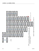
parameter or information to be changed. Refer to the flow
chart for what menus are available within the top level
menus. You may only view the personality settings for
selected menus while in access level 2. Remember, you
may always cancel a selected menu item by pressing the
ESC.
key.
HELP:
PRESS ENTER
LOGGED HELP
1: STARTUP ( 2/ 1)
Summary of Contents for JLG E400AJP
Page 2: ......
Page 32: ...SECTION 1 SPECIFICATIONS 1 18 JLG Lift 3121827 NOTES...
Page 42: ...SECTION 2 GENERAL 2 10 JLG Lift 3121827 NOTES...
Page 54: ...SECTION 3 CHASSIS TURNTABLE 3 12 JLG Lift 3121827 Figure 3 3 Speed Sensor Orientation...
Page 60: ...SECTION 3 CHASSIS TURNTABLE 3 18 JLG Lift 3121827 Figure 3 7 Steering Components and Spindles...
Page 62: ...SECTION 3 CHASSIS TURNTABLE 3 20 JLG Lift 3121827 Figure 3 9 Tilt Sensor Location...
Page 86: ...SECTION 3 CHASSIS TURNTABLE 3 44 JLG Lift 3121827 Figure 3 16 Swing Components...
Page 88: ...SECTION 3 CHASSIS TURNTABLE 3 46 JLG Lift 3121827 Figure 3 18 Battery Cable Connections...
Page 90: ...SECTION 3 CHASSIS TURNTABLE 3 48 JLG Lift 3121827 Figure 3 20 On Board Generator...
Page 97: ...SECTION 3 CHASSIS TURNTABLE 3121827 JLG Lift 3 55 Figure 3 22 Generator Components...
Page 116: ...SECTION 3 CHASSIS TURNTABLE 3 74 JLG Lift 3121827 NOTES...
Page 127: ...SECTION 4 BOOM PLATFORM 3121827 JLG Lift 4 11 Figure 4 10 Boom Limit Switches...
Page 140: ...SECTION 4 BOOM PLATFORM 4 24 JLG Lift 3121827 Figure 4 13 Rotator Counterbalance Valve...
Page 178: ...SECTION 5 HYDRAULICS 5 24 JLG Lift 3121827 Figure 5 26 HydraForce Cartridge Torque Value Chart...
Page 214: ...SECTION 6 JLG CONTROL SYSTEM 6 34 JLG Lift 3121827 NOTES...
Page 257: ......

