SECTION 4 - BOOM & PLATFORM
3121827
– JLG Lift –
4-1
SECTION 4. BOOM & PLATFORM
4.1 BOOM MAINTENANCE
Removal
1.
Remove the platform/support as follows:
a.
Disconnect electrical cable from control con-
sole.
b.
Using an overhead crane or suitable lifting
device, strap support the platform/support.
c.
Remove hardware from pin #1. Using a suitable
brass drift and hammer, remove pin #1 from the
platform support.
d.
Supporting the platform/support, remove the
hardware from pin #2. Using a suitable brass
drift and hammer, remove pin #2 from the fly
boom and remove the rotator.
e.
Supporting the slave cylinder, remove the hard-
ware from pin #3. Using a suitable brass drift
and hammer, remove pin #3 from the fly boom.
f.
Tag and disconnect hydraulic lines to the slave
leveling cylinder. Use a suitable container to
retain any residual hydraulic fluid. Cap hydraulic
lines and ports. Remove the slave cylinder.
2.
Remove the boom from upright as follows:
a.
Remove hardware securing the cover plate on
the side of the base boom section and remove
hose clamps. Disconnect wiring harness from
ground control harness connector.
HYDRAULIC LINES AND PORTS SHOULD BE CAPPED IMMEDI-
ATELY AFTER DISCONNECTING LINES TO AVOID ENTRY OF CON-
TAMINANTS INTO SYSTEM.
b.
Tag and disconnect hydraulic lines from boom
to control valve. Use a suitable container to
retain any residual hydraulic fluid. Cap hydraulic
lines and ports.
c.
Using a suitable lifting equipment, adequately
support boom weight along entire length.
d.
Remove hardware securing the lift cylinder pin
#1. Using a suitable brass drift and hammer,
remove pin #1 from the base boom.
e.
Remove hardware securing the master cylinder
pin #2. Using a suitable brass drift and hammer,
remove pin #2 from the base boom.
f.
Remove hardware securing the base boom pin
#3. Using a suitable brass drift and hammer,
remove pin #3 from the upright.
g.
Using all applicable safety precautions, carefully
lift boom assembly clear of upright and lower to
ground or suitable supported work surface.
Disassembly
1.
Loosen jam nuts on aft end of fly boom wear pad
adjustment and loosen adjustments.
2.
Using a portable power source, attach hose to tele-
scope cylinder port block. Using all applicable
safety precautions, activate hydraulic system and
extend cylinder to gain access to cylinder rod pin
#1. Shut down hydraulic system.
3.
Carefully disconnect hydraulic hose from retract port
of cylinder. There will be initial weeping of hydraulic
fluid which can be caught in a suitable container.
After initial discharge, there should be no further
leakage from the retract port.
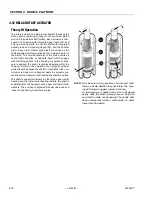
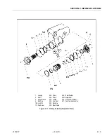
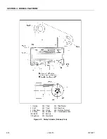
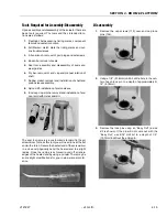
Figure 4-1. Location of Components - Boom Removal
Summary of Contents for JLG E400AJP
Page 2: ......
Page 32: ...SECTION 1 SPECIFICATIONS 1 18 JLG Lift 3121827 NOTES...
Page 42: ...SECTION 2 GENERAL 2 10 JLG Lift 3121827 NOTES...
Page 54: ...SECTION 3 CHASSIS TURNTABLE 3 12 JLG Lift 3121827 Figure 3 3 Speed Sensor Orientation...
Page 60: ...SECTION 3 CHASSIS TURNTABLE 3 18 JLG Lift 3121827 Figure 3 7 Steering Components and Spindles...
Page 62: ...SECTION 3 CHASSIS TURNTABLE 3 20 JLG Lift 3121827 Figure 3 9 Tilt Sensor Location...
Page 86: ...SECTION 3 CHASSIS TURNTABLE 3 44 JLG Lift 3121827 Figure 3 16 Swing Components...
Page 88: ...SECTION 3 CHASSIS TURNTABLE 3 46 JLG Lift 3121827 Figure 3 18 Battery Cable Connections...
Page 90: ...SECTION 3 CHASSIS TURNTABLE 3 48 JLG Lift 3121827 Figure 3 20 On Board Generator...
Page 97: ...SECTION 3 CHASSIS TURNTABLE 3121827 JLG Lift 3 55 Figure 3 22 Generator Components...
Page 116: ...SECTION 3 CHASSIS TURNTABLE 3 74 JLG Lift 3121827 NOTES...
Page 127: ...SECTION 4 BOOM PLATFORM 3121827 JLG Lift 4 11 Figure 4 10 Boom Limit Switches...
Page 140: ...SECTION 4 BOOM PLATFORM 4 24 JLG Lift 3121827 Figure 4 13 Rotator Counterbalance Valve...
Page 178: ...SECTION 5 HYDRAULICS 5 24 JLG Lift 3121827 Figure 5 26 HydraForce Cartridge Torque Value Chart...
Page 214: ...SECTION 6 JLG CONTROL SYSTEM 6 34 JLG Lift 3121827 NOTES...
Page 257: ......


