SECTION 4 - BOOM & PLATFORM
4-12
– JLG Lift –
3121827
4.12 HELAC ROTARY ACTUATOR
Theory Of Operation
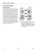
The rotary actuator is a simple mechanism that uses the
sliding spline operating concept to convert linear piston
motion into powerful shaft rotation. Each actuator is com-
posed of a housing with integrated gear teeth (01) and
only two moving parts: the central shaft with integrated
bearing tube and mounting flange (02), and the annular
piston sleeve (03). Helical spline teeth machined on the
shaft engage matching splines on the in-side diameter of
the piston. The outside diameter of the piston carries a
second set of splines, of opposite hand, which engage
with matching splines in the housing. As hydraulic pres-
sure is applied, the piston is displaced axially within the
housing -similar to the operation of a hydraulic cylinder
while the splines cause the shaft to rotate. When the con-
trol valve is closed, oil is trapped inside the actuator, pre-
venting piston movement and locking the shaft in position.
The shaft is supported radially by the large upper radial
bearing and the lower radial bearing. Axially, the shaft is
separated from the housing by the upper and lower thrust
washers. The end cap is adjusted for axial clearance and
locked in position by set screws or pins.
NOTE:
Bars indicate starting positions of piston and shaft.
Arrows indicate direction they will rotate. The hous-
ing with integral ring gear remains stationary.
As fluid pressure is applied, the piston is displaced
axially while the helical gearing causes the piston
and shaft to rotate simultaneously. The double helix
design compounds rotation: shaft rotation is about
twice that of the piston.
Summary of Contents for JLG E400AJP
Page 2: ......
Page 32: ...SECTION 1 SPECIFICATIONS 1 18 JLG Lift 3121827 NOTES...
Page 42: ...SECTION 2 GENERAL 2 10 JLG Lift 3121827 NOTES...
Page 54: ...SECTION 3 CHASSIS TURNTABLE 3 12 JLG Lift 3121827 Figure 3 3 Speed Sensor Orientation...
Page 60: ...SECTION 3 CHASSIS TURNTABLE 3 18 JLG Lift 3121827 Figure 3 7 Steering Components and Spindles...
Page 62: ...SECTION 3 CHASSIS TURNTABLE 3 20 JLG Lift 3121827 Figure 3 9 Tilt Sensor Location...
Page 86: ...SECTION 3 CHASSIS TURNTABLE 3 44 JLG Lift 3121827 Figure 3 16 Swing Components...
Page 88: ...SECTION 3 CHASSIS TURNTABLE 3 46 JLG Lift 3121827 Figure 3 18 Battery Cable Connections...
Page 90: ...SECTION 3 CHASSIS TURNTABLE 3 48 JLG Lift 3121827 Figure 3 20 On Board Generator...
Page 97: ...SECTION 3 CHASSIS TURNTABLE 3121827 JLG Lift 3 55 Figure 3 22 Generator Components...
Page 116: ...SECTION 3 CHASSIS TURNTABLE 3 74 JLG Lift 3121827 NOTES...
Page 127: ...SECTION 4 BOOM PLATFORM 3121827 JLG Lift 4 11 Figure 4 10 Boom Limit Switches...
Page 140: ...SECTION 4 BOOM PLATFORM 4 24 JLG Lift 3121827 Figure 4 13 Rotator Counterbalance Valve...
Page 178: ...SECTION 5 HYDRAULICS 5 24 JLG Lift 3121827 Figure 5 26 HydraForce Cartridge Torque Value Chart...
Page 214: ...SECTION 6 JLG CONTROL SYSTEM 6 34 JLG Lift 3121827 NOTES...
Page 257: ......


